 Facebook
 Google
 GitHub
 Linkedin
Introduction to Image Sensor Technology, from Photons to Electrons
This article, the first in a series, discusses light-sensitive electronic devices called photodiodes and compares CCD and CMOS sensors.
At this point, it is axiomatic that electronic circuitry has replaced film as the primary means of recording light. Hundreds of millions, if not billions, of people live within arm’s reach of a smartphone that is also a camera, and many of those individuals may have only vague ideas about the possibility of taking photos with a film-based camera instead of an electronic device.
Furthermore, the importance of digital imaging goes far beyond smartphone culture and even professional photography or videography. All of my experience in the design of digital cameras occurred within the defense industry, and various other sectors—manufacturing, security, health care, and environmental science come to mind—depend upon various types of image sensors.
Photons and Electrons
The fundamental premise of electronic imaging is that light can be converted into electrical energy in a way that retains visual information and thereby allows us to reconstruct the optical characteristics of a scene. This predictable interaction between photons and electrons initiates the process of capturing a digital image. After the energy delivered by incident photons has been converted into electrical energy, the system must have some way of quantifying this energy and storing it as a sequence (or a matrix) of numerical values.
In most image sensors, the conversion from light to electricity is accomplished by a photodiode, which is a pn junction whose structure favors the production of electron-hole pairs in response to incident light.

Photodiodes are commonly made from silicon, but other semiconductor materials (such as indium arsenide, indium antimonide, and mercury cadmium telluride) are used in various specialized applications.
The Pinned Photodiode
An important advancement in image sensor technology occurred when researchers created something called a pinned photodiode. In the above diagram, the photodiode is like a normal diode in that it consists of one p-type region and one n-type region.
A pinned photodiode has an additional region made from highly doped p-type (abbreviated p+) semiconductor; as shown in the diagram, it is thinner than the other two regions.

This diagram conveys the structure of a pinned photodiode integrated into an image sensor.
The introduction of the pinned photodiode in the 1980s solved a problem (called “lag”) associated with delayed transfer of light-generated charge. Pinned photodiodes also offer high quantum efficiency, improved noise performance, and low dark current (we’ll return to these concepts later in this series).
Nowadays, the light-sensitive elements in almost all CCD and CMOS image sensors are pinned photodiodes.
Types of Image Sensors
The two dominant imaging technologies are CCD, which stands for charge-coupled device, and CMOS (you probably already know what CMOS stands for). Other types do exist: NMOS sensors are used for spectroscopy, microbolometers provide infrared sensitivity for thermal imaging, and specialized applications may use a photodiode array connected to custom amplifier circuitry.
Nevertheless, we’ll focus on CCD and CMOS. These two general sensor categories cover a very wide range of applications and capabilities.
CCD vs. CMOS
It seems that human nature is attracted to value judgments of the “which is better?” variety. Surface mount or through-hole? BJT or FET? Canon or Nikon? Windows or Mac (or Linux)? There is rarely a meaningful answer to such questions, and even comparing individual characteristics can be difficult.
So then, which is better, CMOS or CCD? (Sigh.) The traditional comparison goes something like this: CCDs have lower noise, better pixel-to-pixel uniformity, and a general reputation for superior image quality. CMOS sensors offer higher levels of integration—which reduces the complexity of the circuit designer’s task—and lower power consumption.
I’m not saying that this evaluation is inaccurate, but its utility is limited. Much depends on what you need from a sensor and what your requirements and priorities are.
Furthermore, I’m hesitant to even present these comparisons, for two reasons: First, technology changes quickly, and the immense amounts of money poured into digital-imaging R&D could be gradually reformulating the CCD vs. CMOS landscape.
Second, an image sensor doesn’t produce an image; it’s one component (a very important component, to be sure) in a digital-imaging system, and the perceived image quality produced by a system depends on much more than just a sensor. I don’t doubt that CCDs outperform CMOS sensors with regard to certain optoelectronic properties, but it seems somewhat reductive to associate CCDs with superior overall image quality.
System Considerations
A CCD-sensor-based system requires a serious investment of design effort. CCDs need various non-logic-level supply and control voltages (including negative voltages), and the timing sequences that must be applied to the sensor can be quite complex. The image “data” produced by the sensor is an analog waveform that requires careful amplification and sampling, and of course any signal-processing or data-conversion circuitry is an opportunity to introduce noise.
Low-noise performance begins with the CCD, but it doesn’t end there—we have to strive to minimize noise throughout the signal chain.

This is an example of a CCD output waveform. We’ll talk about this diagram more in a future article.
CMOS image sensors are a very different story. They operate much more like a standard integrated circuit, with logic-level voltage supplies, on-chip image processing, and digital output data. You may have some additional image noise to deal with, but in many applications, that is a small price to pay for a major reduction in design complexity, development cost, and stress.
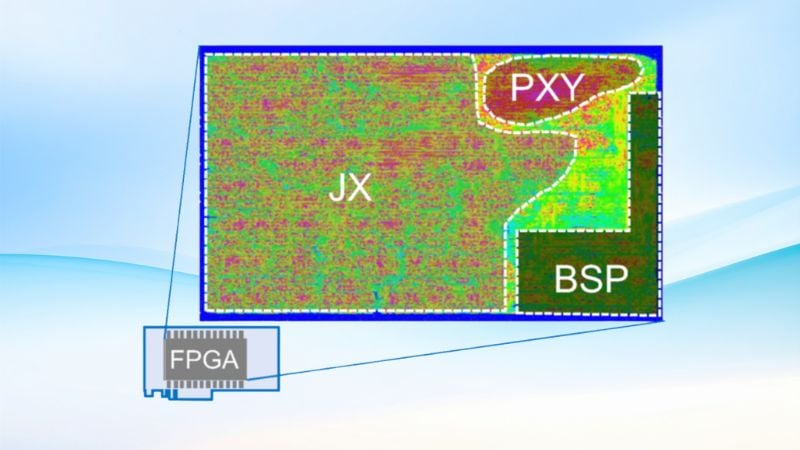
Image processing is not a task for a typical microcontroller, and it’s particularly demanding when you’re working with high frame rates or a high-resolution sensor. Most applications will benefit from the computing power of a digital signal processor or an FPGA.
You’ll also want to think about compression, especially if you need to store images in memory or transfer them wirelessly. This can be performed in software or programmable hardware, but in my opinion the ADV212—a JPEG compression/decompression ASIC from Analog Devices—is an excellent option.
Conclusion
There is much more that could be said about this interesting and expansive topic, but I think that we’ve laid a solid foundation for the rest of this series. In the next article, we’ll take a closer look at the functionality of CCD image sensors.
Related Content


Robert,
You started your first is a series. I like your clarity and images, but you skipped something rather important.
Where are you going with your series? What is it leading to? What do you hope to accomplish?
Your latency related hints cover people wanting to build more standard cameras. Stick one in a cell phone, add one to a security network, put some into an industrial application. But I want to program my own low-latency, “inside the loop” algorithms. I do not want lossy jpeg.
My application has to be lossless, and because the signal is complex, I need flexibility to develop and test my own algorithms. If it goes like usual, that means hundreds of variations until I find the most suitable, and efficient algorithms, for the particular datastreams for these scenes and lighting levels. It it takes an hour to run full resolution data, several hours to process and experiment with statistical summaries that characterize the signal variations and stable states, then many hours to get a new algorithm into a processor close enough to pick up the data and run in real time—then it is essentially impossible, without many parallel researchers whom I cannot afford.
So you pointed to off-the-shelf jpeg compression. Do you have any sugggestions for lossless and statistical methods that are also lossless? All the true AI methods are going to be real-time - once the sensor has been trained. I am focussing on the initial phase of that process - gathering complete training sets at full resolution, then running simple standard statistical algorithms as proxies for the compiled and efficient application-specific algorithms that run in real-time next to the sensor. These feed back very very specific data relevant to the whole network and its lossless operation.
I am going back through all the mathematics and physics and models for what constitutes a diode. It is a mess. Everyone is taking shortcuts. Everyone is giving “rule-of-thumb” and “hints” and “clues”. I do not have that much time to work with partial models, especially if they are just incomplete rehashes.
Do you have any suggestions for where to find calibration methods for the sensors? I find it common to have to run several years worth of data from many sensors of the same type just to get a decent lossless compression algorithm that fits a particular data stream.
Now it says that you wrote this three days ago, but I just got the email today.
Your diagram of a pinned photodiode has no quantitative information. There must be someone who knows every electron and hole and atom of these things. I will be looking. I have even more time than usual, since we are locked in waiting for people to learn to track infectious disease cases. I ordered several books on semiconductor physics, but realize they are all coming from cities under quarantine, or nearly so.
Good luck.
Richard Collins, The Internet Foundation