Facebook
 Google
 GitHub
 Linkedin
Introduction to the I2S Interface
This article discusses the characteristics and applications of a serial communication protocol intended specifically for audio systems.
I2S and the Age of Digital Audio
The growing collection of commonly used electrical-engineering abbreviations can be a bit overwhelming at times, and I won’t hold it against you if you’ve seen the term “I2S” a few times and just assumed that it was simply a typographically erroneous version of “I2C.”
There is indeed some relationship between these two protocols. Both were initially developed by Philips Semiconductors (now NXP), and both begin with “I2” because they are intended for inter-IC communication. However, I2S was released after I2C, and whereas I2C is a generic interface, I2S is designed for transporting audio data—the “S” in the name stands for “sound.”
I2S was created in the 1980s, when digital was beginning its conquest of the consumer-audio market. The stated purpose of I2S is to facilitate the development of audio electronics by means of a standardized interface for transmission of digital data among ADCs, DACs, digital filters, digital signal processors, and other types of ICs used in audio systems. It is inherently a two-channel protocol, because it was designed for stereophonic sound (that’s the fancy name for what we call “stereo”).
Characteristics of I2S
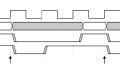
The following diagram depicts three configurations supported by I2S.

Diagram taken from the I2S specification, first published by Philips Semiconductors in 1986 and revised in 1996.
Data is driven on the SD line, the state of the WS line corresponds to the audio channel (right or left) that is currently being transmitted, and the clock line carries the serial clock. As you can see in the diagram, the WS and SCK signals can be generated by the transmitter, the receiver, or a third-party controller component.
The following lists identify salient characteristics of the three I2S signals.
Serial Data (SD)
- Digital values are transmitted MSb first.
- Transmitter and receiver do not need to have an agreed-upon word length; the transmitter sends what it has, and the receiver takes what it can use.
- New data bits can be clocked out on the rising or falling edge of the clock. However, they must be clocked in on the rising edge, so the more straightforward approach here is the arrangement shown in the diagram below—i.e., we clock data out on the falling edge and we clock it in on the rising edge.
- The protocol does not include unused clock periods between words; the LSb of one word is followed immediately by the MSb of the next word.
Word Select (WS)
- A logic low on WS indicates that the word currently being transferred is part of the data stream for the left audio channel; logic high on WS indicates right-channel audio.
- To facilitate data handling on both the transmitter and the receiver side, the WS signal transitions one clock period before the completion of a data word:

Diagram taken from the I2S specification.
Clock
- The protocol does not specify a maximum data rate.
- The clock runs continuously.
I2C vs. I2S
If you’re familiar with the I2C protocol, you may have realized by now that I2C and I2S are much less similar than their names would suggest.
I2C doesn’t emphasize high data rates, and it involves handshaking features that allow it to function effectively and reliably in (potentially large) networks consisting of various different types of ICs. As conveyed by the following diagram, a lot of things can go wrong in this type of communication environment, and the complexity of the I2C protocol reflects the complexity of the task for which it is intended.

I2S, on the other hand, is designed to efficiently move a specific type of digital data. Transfer speed is more important, since real-time serialized transmission of high-resolution, two-channel audio requires much more bandwidth than communication tasks that are often accomplished via I2C (or UART).
The point-to-point nature of I2S transmission eliminates the need for I2C’s pullup resistors, and using a third signal for word-level synchronization allows us to dispense with the protocol details that help I2C maintain data organization in a two-wire bus.
I2S is more like SPI than I2C. In fact, an SPI implementation intended for unidirectional data transmission uses essentially the same configuration: one signal for the clock, one for data, and a third for word-level synchronization.
Conclusion
I2S is an efficient, straightforward serial-communication protocol that is great for digitized audio. However, there’s no law saying that it is limited to audio data. I used it years ago to implement a prototype software-defined radio; I2S offered transfer speed sufficient for baseband signals and was conveniently incorporated into the DSP development platform that I was working with.
If you have any suggestions for I2S applications, leave a comment and let us know!
Related Content