 Facebook
 Google
 GitHub
 Linkedin
Back to Basics: The Universal Asynchronous Receiver/Transmitter (UART)
This technical brief explains some low-level details of the widespread—I might even say ubiquitous—UART communication interface.
This technical brief explains some low-level details of the widespread—I might even say ubiquitous—UART communication interface.
Related Information
There are probably few among the world’s electrical engineers and electronics enthusiasts who have not interacted in some way with a universal asynchronous receiver/transmitter (UART) interface. In a world where technology can become obsolete very quickly, we have to give credit to whoever created this simple digital communication scheme, which has been around for decades and still enjoys immense popularity.
Note: The term “UART” is rather vague. Various aspects of the interface—number of data bits, number of stop bits, logic levels, parity—can be adapted to the needs of the system. In this article, I will focus on UART implementations that are commonly found in modern microcontroller applications.
Capabilities and Characteristics
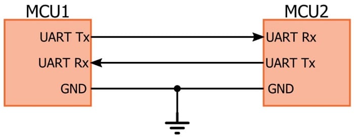
As you probably know, a basic UART system provides robust, moderate-speed, full-duplex communication with only three signals: Tx (transmitted serial data), Rx (received serial data), and ground. In contrast to other protocols such as SPI and I2C, no clock signal is required because the user gives the UART hardware the necessary timing information.
Actually, there is a clock signal, but it is not transmitted from one communicating device to the other; rather, both receiver and transmitter have internal clock signals that govern how the changing logic levels are generated (on the Tx side) and interpreted (on the Rx side). Unsurprisingly, UART communication doesn’t work if the transmitter and receiver have been configured for different data-transmission frequencies. Also, the internal clock signals must be 1) sufficiently accurate relative to the expected frequency and 2) sufficiently stable over time and temperature.
Key Terms
Let’s review some terminology and, in the process, we’ll cover more UART characteristics:
- Start bit: The first bit of a one-byte UART transmission. It indicates that the data line is leaving its idle state. The idle state is typically logic high, so the start bit is logic low.
- The start bit is an overhead bit; this means that it facilitates communication between receiver and transmitter but does not transfer meaningful data.
- Stop bit: The last bit of a one-byte UART transmission. Its logic level is the same as the signal’s idle state, i.e., logic high. This is another overhead bit.

- Baud rate: The approximate rate (in bits per second, or bps) at which data can be transferred. A more precise definition is the frequency (in bps) corresponding to the time (in seconds) required to transmit one bit of digital data. For example, with a 9600-baud system, one bit requires 1/(9600 bps) ≈ 104.2 µs. The system cannot actually transfer 9600 bits of meaningful data per second because additional time is needed for the overhead bits and perhaps for delays between one-byte transmissions.

- Parity bit: An error-detection bit added to the end of the byte. There are two types—“odd parity” means that the parity bit will be logic high if the data byte contains an even number of logic-high bits, and “even parity” means that the parity bit will be logic high if the data byte contains an odd number of logic-high bits. This may seem counterintuitive, but the idea is that the parity bit ensures that the number of logic-high bits is always even (for even parity) or odd (for odd parity). So if you’re using even parity and the byte has three logic-high bits, the parity bit will be logic high, so that the total number of logic-high bits in the transmitted data (i.e., the byte itself plus the parity bit) is even.
- By forcing the number of logic-high bits to be always even (for even parity) or odd (for odd parity), the parity bit provides a crude error-detection mechanism—if a bit gets flipped somewhere in the transmission process, the number of logic-high bits won’t match the chosen parity mode. Of course, the strategy breaks down if two bits are flipped, so the parity bit is far from bulletproof. If you have a serious need for error-free communication, I recommend a CRC.
Synchronizing and Sampling
Standard digital data is meaningless without a clocking mechanism of some kind. The following diagram shows you why:

A typical data signal is simply a voltage that transitions between logic low and logic high. The receiver can correctly convert these logic states into digital data only if it knows when to sample the signal. This can be easily accomplished using a separate clock signal—for example, the transmitter updates the data signal on every rising edge of the clock, and then the receiver samples the data on every falling edge.
However, as implied by the name “universal asynchronous receiver/transmitter,” the UART interface does not use a clock signal to synchronize the Tx and Rx devices. So how does the receiver know when to sample the transmitter’s data signal?
The transmitter generates a bit stream based on its clock signal, and then the receiver’s goal is to use its internal clock signal to sample the incoming data in the middle of each bit period. Sampling in the middle of the bit period is not essential, but it is optimal, because sampling closer to the beginning or end of the bit period makes the system less robust against clock-frequency differences between receiver and transmitter.
The receiver sequence begins with the falling edge of the start bit. This is when the critical synchronization process occurs. The receiver’s internal clock is completely independent from the transmitter’s internal clock—in other words, this first falling edge can correspond to any point in the receiver’s clock cycle:

To ensure that an active edge of the receiver clock can occur near the middle of the bit period, the frequency of the baud-rate clock sent to the receiver module is much higher (by a factor of 8 or 16 or even 32) than the actual baud rate.
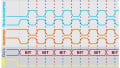
Let’s say that one bit period corresponds to 16 receiver clock cycles. In this case, synchronization and sampling can proceed as follows:
- The receive process is initiated by the falling edge of the start bit.
- The receiver waits for 8 clock cycles, in order to establish a sampling point that is near the middle of the bit period.
- The receiver then waits 16 clock cycles, which brings it to the middle of the first data-bit period.
- The first data bit is sampled and stored in the receive register, and then the module waits another 16 clock cycles before sampling the second data bit.
- This process repeats until all data bits have been sampled and stored, and then the rising edge of the stop bit returns the UART interface to its idle state.

Conclusion
This article has covered some details about a communication protocol that you perhaps have successfully used many times. It is quite possible to implement a UART interface while knowing very little about the actual behavior of the signals and hardware, but a little extra knowledge—aside from the general edification that such knowledge provides—can be helpful when your UART communication isn’t working as expected.
Related Content


Nice article
So with the parity bit your only transmitting 7 bits of information? Or do i need to refresh my knowledged of grey code or 2s complimant?