 Facebook
 Google
 GitHub
 Linkedin
Low-Pin-Count Serial Communication: Introduction to the 1-Wire Bus
The 1-wire bus, though not as widespread as other protocols, is a valuable communication technique for certain applications.
Serial communication is a reduced-signal-count alternative to parallel interfaces. By transferring bits sequentially instead of simultaneously, serial connections can, in theory, reduce a parallel bus of any size down to one pin. In practice, however, serial protocols tend to use more than one pin because we can make communication more convenient and robust by incorporating additional signals.
SPI, for example, includes a serial clock signal and a slave-select signal, and it uses two data signals to provide full-duplex communication.
I2C enables robust, flexible, half-duplex communication using only two signals (data and clock) that operate within the context of highly organized transactions.
UART is a simple, reliable interface that requires only a data signal, but we’ll see later that the 1-wire bus is more deserving of the “one wire” label than UART.
1-Wire Basics
The 1-wire bus was developed by Dallas Semiconductor, and Dallas was acquired by Maxim, so as far as I know Maxim is the current “owner” of the protocol. The interface uses a master/slave structure, and the only required connections between master and slave are the ground reference and one signal line. As with I2C, the signal line is pulled up to VDD through a resistor and driven via open-drain output circuitry.
The 1-wire-bus emphasizes low pin count over speed or implementation flexibility. The original protocol was limited to a data rate of 16.3 kbps, which seems absurdly slow by current standards but is, nevertheless, perfectly adequate for many applications. Newer 1-wire devices support a higher-speed “overdrive” mode.

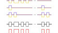
This is the basic 1-wire-bus configuration.
As you may have guessed, the 1-wire bus does not support full-duplex communication. (It would be quite a neat trick to simultaneously transfer separate data streams in two directions over one wire.) It is bidirectional, though.
Momentary Contact Applications
A distinctive aspect of the 1-wire protocol is that it is intended for use in (to use Maxim’s terminology) “momentary contact environments.” When I think about I2C and especially SPI, I imagine a PCB with various integrated circuits that are permanently installed and linked via permanent connections.
The 1-wire bus, though, is often used with components that are in electrical contact with the master only temporarily. The importance of momentary contact systems in 1-wire-bus implementations is reflected in the “iButton” package (see the photo below). This is one of the standard form factors for 1-wire-bus components and serves as a durable, standardized housing for slave devices that are frequently separated from the master device.

The iButton package has a diameter of 16 mm and is made of stainless steel. It provides convenient connection to the master and protects the 1-wire IC from harsh conditions. Image courtesy of Maxim.
Parasitic Power
The most interesting feature of the 1-wire bus, in my opinion, is the “parasite power supply.” At the beginning of this article I mentioned that the 1-wire protocol is closer to a truly one-wire interface than UART is. My justification for this assertion is that 1-wire slaves do not require a power connection, whereas with UART both the receiver and the transmitter must have separate connections to a power supply.
How on earth do 1-wire integrated circuits—these include temperature sensors, authenticators, memory, and data loggers—function and communicate without a power-supply pin? Well, actually, they do have a power-supply pin, because the “one wire” between master and slave is capable of transferring both data and power.
A 1-wire IC can extract operating power from a serial-data signal by means of an internal power-supply circuit consisting of a diode and a capacitor. When the data line is logic high, some extra current is used to charge the capacitor, and then the diode prevents the capacitor from discharging when the data line is logic low.

Diagram courtesy of Maxim.
Identifying Slave Devices
Another interesting feature of the 1-wire protocol is its method of addressing the components that are connected to the bus. Every 1-wire device is preprogrammed with a unique and permanent 64-bit serial number. (Credit to Dallas Semiconductor for good long-term planning; 264 is equal to approximately 18.4 quintillion, so I don’t think that we’ll be running out of 1-wire addresses anytime soon.) This 64-bit serial number includes 8 bits for a CRC and 8 bits for a code that identifies the family to which the IC belongs.
The master uses these 64-bit serial numbers when addressing slaves, which means that there’s no possibility that multiple devices on a bus will have the same slave address.
Addressing slaves is easy enough if the serial numbers are known and incorporated into the master’s firmware, but what happens if they are not known? Well, the 1-wire protocol incorporates a handy search algorithm that allows the master to determine the serial numbers of all connected devices. If you’re interested in the details of the 1-wire search procedure, this document from Maxim provides an abundance of further information.
Conclusion
I hope that this article has given you a clear overview of what the 1-wire bus is and how it is used. If you have ever incorporated this protocol into one of your designs, it would be great to hear about your experiences. Why did you choose 1-wire instead of SPI or UART? Did you notice any significant advantages or disadvantages?
Related Content


Thanks for an interesting article. I built into a very simple system using this exact same architecture before I was even aware that it was an existing standard. It’s in an odd low key area. As well as working in electronics I’m a long standing guitarist. I use mainly Marshall amplification, (everyone will know the name I suspect). I have a JVM model by Marshall which has a floor based control unit to make changes to the amp’s setup while you play. The floor unit had 4 stomp switches but 6 amp functions to control so switch designation was made programmable from the amp end. I wanted to expand its capabilities to be able to access all of the amp’s functionality as I played so I hacked Marshall’s comms system.
As hardware, I found the system you describe in there to the “T”. Maxim’s diagram could have been drawn for the amp with the lack of the 64bit ID. The units are connected via a simple single core 1/4” jack lead, much like a guitar lead but using a more basic cable type as no screening is required. The amp master was based around an ATMega8 chip and the floor unit slave around the AT2313. These simply swapped a pair of 8bit bytes of data to define the whole desired configuration every time a change was made. It was a cinch to set up a new unit, (based around an Arduino Nano for ease of home build and programming), which took the place of the AT2313 and could respond to 6 switches and even output the current configuration to an additional simple display panel on the floor too.
On starting your article I expected to find your single wire comm setup out there in the real world in areas I am familiar with, but to find it so close to home in something as mundane as my old Marshall amp was quite a surprise. Sure MIDI is the modern (sic!) standard for this task in musical applications but this single wire system is absolutely solid rock reliable and so easy to implement and service in my case it is a very sensible choice.
There is another 1-wire bus protocol used in Texas Instrument temperature sensor TMP107. This bus is much more modern, faster and communicates on distance not 5 meters but 500+ meters. And it also can work without the power supply line. Contrary to Maxim bus, it doesn’t need a special bus controller. It using for communication the standard UART port, where the two wires are “combined” in one. And if need you can put up to 32 parts on a line.