Facebook
 Google
 GitHub
 Linkedin
The Basics Behind a MEMS Capacitive Humidity Sensor
Learn the basics of MEMS capacitive humidity sensors, namely their structure, performance metrics, dew point, and applications.
For many applications, advances in MEMS IC technology have transformed the complex art of humidity measurement into a simple, low-cost sensor. These sensors may not serve every application; however, they do work well in relatively clean extended-ambient conditions. Weather monitoring and air conditioning might be the obvious choice, though others include humidity control for food storage, warehousing, and printing. Furthermore, industrial processes such as chemical and pharmaceutical manufacture are best done in controlled humidities, and electronics assembly needs to avoid low humidities to prevent static discharge damage.
In this article, we'll go over some basics of humidity measurement using capacitance sensing, typical types of MEMS humidity sensors, their performance, applications, and other considerations.
Capacitive Humidity Sensor Measurement Basics
Humidity is sensed by capacitance using moisture-sensitive dielectrics. Figure 1 illustrates the high-level construction basics of a capacitive humidity sensor.

Figure 1. A capacitive humidity sensor's basic structure. Image used courtesy of XY
When creating a capacitive humidity sensor, an electrode is first deposited on a substrate, usually silicon. Next, a thin humidity-sensitive dielectric layer, usually polymer, is deposited, and the second electrode, moisture-permeable, is added on top. Finally, the sensor is covered with a permeable layer to protect it from contamination and condensation. MEMS IC sensors include the circuitry necessary to convert the capacitance measurement to a digital or analog output and are manufactured using IC methods.
The water molecule is highly polarized (with a dielectric constant of around 80), which can be much higher than polymers. When the dielectric absorbs water vapor, its dielectric constant increases, thus increasing the capacitance. At lower humidity, the dielectric gives up some water, and the capacitance goes back down. The change is nearly linear with RH (relative humidity) and is only slightly affected by temperature. Long-term stability should be good in normal applications.
Another attribute is that the capacitance is small. Non-MEMS sensors (capacitance only, no electronics) typically specify 200 pF or less and change less than 20% from 0 to 100% RH. A few inches of connecting wire or cable can cause a significant error, as can the measurement circuit’s capacitance. With MEMS sensors, though, the measurement circuitry is built in, and the calibration is based on total capacitance.
A MEMS Humidity Sensor Overview
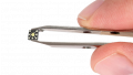
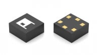
Figure 2 shows two example MEMS sensors.

Figure 2. Example of a typical MEMS IC humidity sensor (left), which is also available with protective covers (right). Image [modified] used courtesy of TI
These sensors generally look like standard surface mount ICs, but with an opening for the sensor. Figure 2 (left) shows the opening, while Figure 2 (right) adds an optional protective filter cover. Typically, these sensors come in sizes that are 2 or 3 mm square and can cost just a few dollars.
Diving deeper, Figure 3 shows an example functional diagram, which includes temperature measurements.

Figure 3. Example MEMS IC humidity sensor measurement system block diagram. Image used courtesy of TI and Mouser
Temperature can be especially useful if you need to compute the dew point (we'll get into this concept in the next section), which requires both RH and temperature. Most ICs also use it internally to compensate for the humidity sensor’s temperature coefficient. It's important to note that most capacitance-based sensors measure RH, not dew point.
Initial calibration data is stored digitally so, as mentioned above, errors such as added capacitance are calibrated out. Along with temperature compensation, the program also corrects the sensor nonlinearities. Almost all sensors use I2C (inter-integrated circuit) serial communication, are usually compatible with the SPI (serial peripheral interface) bus, and some even have analog outputs, which we’ll cover in a bit.
Dew Point vs Relative Humidity
Dew point measures absolute, not relative, humidity. This means that RH varies with temperature, but absolute humidity does not. Converting from one to the other requires temperature and uses complex equations. You can search for “calculate dew point” to find online calculators, like this example one here. Below, Figure 4 shows a dewpoint vs air temperature conversion graph.

Figure 4. An RH dew point conversion graph. Image used courtesy of Easchiff via Wikipedia Commons CC BY-SA 4.0
As an approximation, an RH accuracy of +3% translates to about +0.6 °C (1.1 °F) dew point accuracy.
Typical Humidity Sensor Performance, Features, and Functionality
Below, let's outline some basic performance metrics for general MEMS humidity sensors.
Humidity Measurement Accuracy: these accuracies generally run between ±02% and ±5% RH for humidities between 20% and 80%. The sensors operate from 0% to 100% (noncondensing) but with looser accuracy. Read the specs carefully: some specify typical accuracy, not maximum. Temperature accuracy generally is better than ±1 °C.
Temperature Ranges: most operate at least from -25 °C to +85 °C, some wider. Sometimes the RH accuracy statements don’t cover the full temperature range, though, especially the extreme lows or highs. Some spec sheets are not clear on this.
Calibration: these sensor calibrations can shift slowly over time. A typical specification is ±0.5% RH per year with normal use. Extended time at high humidities can accelerate this performance shift. Contaminants can also cause problems. Some sensors include a heater which can be activated for drift correction.
Response Time: the response time for these types of sensors often depends greatly on airflow. Typical specs are 63% response in 5 to 10 seconds with 1 meter per second airflow. Sensors with protective filter covers will be much slower, and response time may not be specified. This only matters for rapidly changing humidities, such as control systems that use water spray or steam to add humidity.
Challenges: condensation or wet water is a concern, but in clean applications (no contaminants or chemicals) the sensor should eventually recover. A couple of sensors specify 5 or 10-second recovery after condensation. In severe cases, the drift correction heater may be used if your sensor has one.
Just as a note, I found no specifications regarding water in liquid form. The sensor should be properly shielded, which will slow its response. Of course, circuit boards should not get wet anyway.
Analog Outputs: in researching this article, I found only two manufacturers that offer analog outputs on MEMS IC sensors, Sensirion and TE Sensors (Measurement Specialties). Both are digital inside, as in Figure 3, but with digital to analog conversion added to provide analog RH and temperature outputs. There are some older sensors that are purely analog, but they do not include stored calibration, linearization, or temperature compensation.
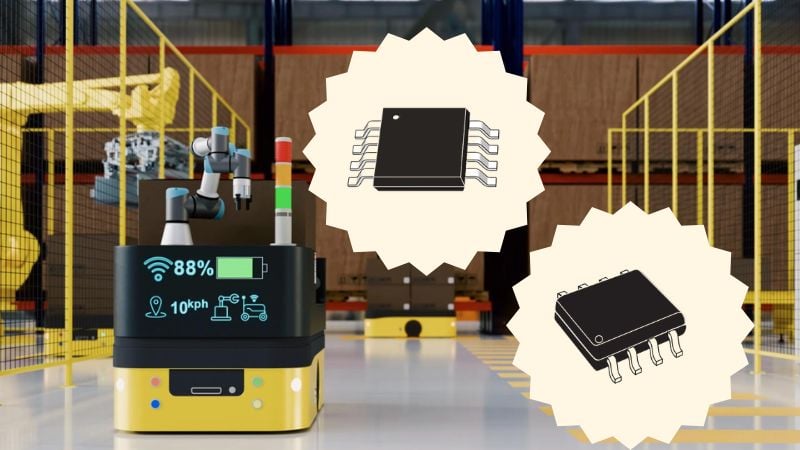
Capacitive MEMS Humidity Sensor Applications
Capacitive MEMS humidity sensors can serve industrial and warehousing applications, not just weather and air conditioning. Speaking from personal experience, I once was involved in a project which used MEMS sensors to control temperature and humidity in large industrial control cabinets. Another example is how the National Weather Service (NWS) switched [PDF] from complex, maintenance-intensive chilled mirror dew point measurement to a custom-modified capacitive sensor for automated airport weather stations.
As mentioned, the most oftenly used application for these types of sensors is air conditioning, which, in the extended sense, can include:
- Humidity control in printing (for best ink adhesion) and in paper storage (to prevent curling, wrinkling, and size change).
- Food storage, especially fruits and vegetables. Humidity control also reduces bacteria growth in meat and fish.
- Pharmaceutical and other manufacturing.
- Static electricity control to avoid potentially damaging or explosion-causing discharges. In electronics assembly, discharges can damage or destroy integrated circuits.
- Woodworking and plastic injection molding can be improved by humidity control.
Humidity Sensor Precautions and Tips
The circuit board assembly is the main precaution to consider regarding humidity sensors. Some tips are:
- Never clean a board with an open sensor on it.
- Use no-clean solder and flux.
- Even if your sensor has a protective filter cover, be careful! Follow the manufacturer’s recommendations.
- Do not allow the conformal coating to get on the sensor.
- Avoid volatile solvents and organic chemicals. The outgassing can upset calibration, sometimes irreversibly.
- Avoid acids, bases, H2O2, and high ozone concentrations.
- Do not direct air blasts at the sensor, especially compressed air which might have oil in it. In other words, keep it clean!
Where to Purchase Humidity Sensors?
The most obvious way to find humidity sensors is to search for "sensors" on electronics distributor websites. As of the date of this article, major manufacturers include, but obviously are not limited to:
- Amphenol Advanced Sensors (Telaire)
- Honeywell
- Sensirion
- Silicon Labs
- TE Sensors (Measurement Specialties)
- Texas Instruments
Hobbyist sites such as SparkFun Electronics, Arduino, and Jameco also have development breakout boards.