 Facebook
 Google
 GitHub
 Linkedin
Introduction to Capacitive Touch Sensing
In this article, we will take a detailed (but not too detailed) look at the electrical principles that allow us to detect the presence of a human finger using little more than a capacitor.
In this article, we will take a detailed (but not too detailed) look at the electrical principles that allow us to detect the presence of a human finger using little more than a capacitor.
Supporting Information
Capacitors Can Be Sensitive
Within the last decade or so, it has become difficult indeed to imagine a world without touch-sensitive electronics. Smartphones are a prominent and ubiquitous example, but of course, there are numerous devices and systems that incorporate touch-sensitive functionality. Both resistance and capacitance can be employed as a means to achieving touch sensitivity; in this article, we will discuss only capacitive touch sensing, which has emerged as the preferred implementation.
Though applications based on capacitive touch sensing can be quite sophisticated, the fundamental principles underlying this technology are fairly straightforward. Indeed, if you understand the nature of capacitance and the factors that determine the capacitance of a particular capacitor, you are well on your way to understanding capacitive touch sensing.
Capacitive touch sensors fall into two general categories: the mutual-capacitance configuration and the self-capacitance configuration. The former, in which the sensing capacitor is composed of two terminals that function as emitting and receiving electrodes, is preferred for touch-sensitive displays. The latter, in which one terminal of the sensing capacitor is connected to ground, is a straightforward approach that is suitable for a touch-sensitive button, slider, or wheel. This article presents the self-capacitance configuration.
The PCB Capacitor
Capacitors come in many forms. We’re all accustomed to seeing capacitance in the form of leaded components or surface-mount packages, but actually, all you really need is two conductors separated by an insulating material (i.e., the dielectric). Thus, it is quite simple to create a capacitor using the conducting layers incorporated into a printed circuit board. For example, consider the following top view and side view representations of a PCB capacitor used as a touch-sensitive button (note that the solder-mask layer is omitted in the side-view diagram).
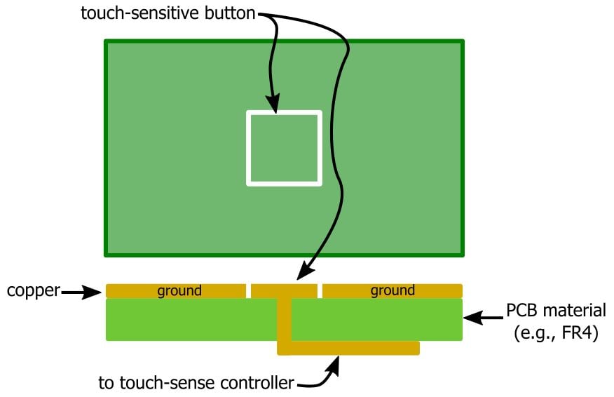
The insulating separation between the touch-sensitive button and the surrounding copper creates a capacitor. In this case, the surrounding copper is connected to the ground node, and consequently, our touch-sensitive button can be modeled as a capacitor between the touch-sensitive signal and ground.
At this point, you might be wondering about how much capacitance this little PCB arrangement really provides. Furthermore, how are we ever going to calculate it accurately. . . ? To answer the first question, the capacitance is very small, maybe around 10 pF. As for the second question: Don’t worry if you’ve forgotten your electrostatics, because the exact value of the capacitor is irrelevant. We are looking only for changes in capacitance, and we can detect these changes without knowing the nominal value of the PCB capacitor.
The Effect of a Finger
So what causes these capacitance changes that the touch-sense controller is going to detect? A human finger, of course.

Before we discuss why the finger changes the capacitance, it is important to understand that there is no direct conduction taking place here; the finger is insulated from the capacitor by the PCB’s solder mask and usually also by a layer of plastic that separates the device’s electronics from the external environment. So the finger is not discharging the capacitor, and furthermore, the amount of charge stored in the capacitor at a particular moment is not the quantity of interest—rather, the quantity of interest is the capacitance at a particular moment.
So then, why does the presence of the finger alter the capacitance? There are two reasons: The first involves the finger’s dielectric properties, and the second involves the finger’s conductive properties.
Finger as Dielectric
We usually think of a capacitor as having a fixed value determined by the area of two conducting plates, the distance between the plates, and the dielectric constant of the material between the plates. We certainly cannot change the physical dimensions of the capacitor just by touching it, but we can change the dielectric constant, because a human finger has different dielectric characteristics than the material (presumably air) that it is displacing. It’s true that the finger will not be located in the actual dielectric region, meaning the insulating space directly between the conductors, but such an “intrusion” into the capacitor itself is not necessary:

As shown in this diagram, the finger does not need to be between the plates to influence the dielectric characteristics because the capacitor’s electric field extends into the surrounding environment.
It turns out that human flesh is quite a good dielectric material because our bodies are mostly water. The dielectric constant of a vacuum is defined as 1, and the dielectric constant of air is just slightly higher (about 1.0006 at sea level and room temperature). The dielectric constant of water is much higher, around 80. So the finger’s interaction with the capacitor’s electric field represents an increase in the dielectric constant and hence an increase in the capacitance.
Finger as Conductor
Anyone who has experienced an electric shock knows that human skin is conductive. I mentioned above that direct conduction between the finger and the touch-sensitive button—i.e., a situation in which the finger discharges the PCB capacitor—does not occur. However, this doesn’t mean that the conductivity of the finger is irrelevant. It is actually quite relevant because the finger becomes the second conductive plate of an additional capacitor:

For practical purposes, we can assume that this new capacitor created by the finger (let’s call it the finger cap) is in parallel with the existing PCB capacitor. This situation is a bit complex because the person using the touch-sensitive device is not electrically connected to the PCB’s ground node, and thus the two capacitors are not “in parallel” in the typical circuit-analysis sense.
However, we can think of the human body as providing a virtual ground because it has a relatively large capacity to absorb electric charge. In any event, we don’t need to worry about the exact electrical relationship between the finger cap and the PCB cap; the important point is that the pseudo-parallel configuration of the two capacitors means that the finger will increase the overall capacitance because capacitors add in parallel.
Thus, we can see that both mechanisms governing the interaction between the finger and the capacitive touch sensor contribute to an increase in capacitance.
Proximity vs. Contact
The preceding discussion leads us to an interesting feature of capacitive “touch” sensing: a measurable change in capacitance can be generated not only by contact between the finger and the sensor but also by proximity between the finger and the sensor. I usually think of a touch-sensitive device as a replacement for a mechanical switch or button, but capacitive sensing technology actually introduces a new layer of functionality by allowing a system to determine the distance between a sensor and a finger.
Both of the capacitance-altering mechanisms described above produce effects that are proportional to distance. For the dielectric-constant-based mechanism, the amount of fleshy dielectric interacting with the capacitor’s electric field increases as the finger moves closer to the conductive portions of the PCB capacitor. For the conductivity-based mechanism, the capacitance of the finger cap (as with any cap) is inversely proportional to the distance between the conducting plates.
Keep in mind, though, that this is not a method for measuring the absolute distance between the sensor and the finger; capacitive sensing does not provide the sort of data that would be needed to perform precise absolute distance calculations. I assume that it would be possible to calibrate a capacitive sense system for rough distance measurements, but since capacitive sense circuitry is designed to detect changes in capacitance, it follows that this technology is particularly suitable for detecting changes in distance, i.e., when a finger is moving closer to or farther from a sensor.
Conclusion
You should now have a solid conceptual foundation upon which to build a soaring edifice of capacitive-touch-sense expertise. We’ll start construction in the next article by looking at implementation techniques that will help you to transition from theory to practice.
Next Article in Series: Circuits and Techniques for Implementing Capacitive Touch Sensing
Related Content


Is it the same concept with a spring key? in that case, does the finger and the spring become plates of an additional capacitor?