Facebook
 Google
 GitHub
 Linkedin
Circuits and Techniques for Implementing Capacitive Touch Sensing
This article presents some basic cap-sense circuit configurations and discusses how to deal with low- and high-frequency noise.
This article presents some basic cap-sense circuit configurations and discusses how to deal with low- and high-frequency noise.
Supporting Information
- Electric Fields and Capacitance
- Factors Affecting Capacitance
- Op-Amp Oscillator Circuits
- Positive Feedback
Previous Article
Measuring Change
If you’ve read the previous article, you know that the essence of capacitive touch sensing is the change in capacitance that occurs when an object (usually a human finger) approaches a capacitor. The presence of a finger increases the capacitance by 1) introducing a substance (i.e., human flesh) with a relatively high dielectric constant and 2) providing a conductive surface that creates additional capacitance in parallel with the existing capacitor.
Of course, the mere fact that the capacitance changes is not particularly useful. To actually perform capacitive touch sensing, we need a circuit that can measure capacitance with enough accuracy to consistently identify the increase in capacitance caused by the presence of the finger. There are various ways to do this, some quite straightforward, others more sophisticated. In this article we will look at two general approaches to implementing capacitive-sense functionality; the first is based on an RC (resistor–capacitor) time constant, and the second is based on shifts in frequency.
The RC Time Constant—Like an Old Friend
If you’re like me, you experience vague feelings of university nostalgia when you see the exponential curve representing the voltage across a charging or discharging capacitor. There’s something about it—maybe that was one of the first times I realized that higher math actually has some relationship to reality, or maybe in this age of grape-harvesting robots there is something appealing about the simplicity of a discharging capacitor. In any event, we know that this exponential curve changes when either resistance or capacitance changes. Let’s say we have an RC circuit composed of a 1 MΩ resistor and a capacitive touch sensor with typical fingerless capacitance of 10 pF.
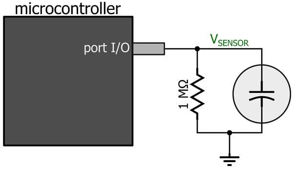
We can use a general-purpose input/output pin (configured as an output) to charge the sensor cap up to the logic-high voltage. Next, we need the capacitor to discharge through the large resistor. It’s important to understand that you cannot simply switch the output state to logic low. An I/O pin configured as an output will drive a logic-low signal, i.e., it will provide the output with a low-impedance connection to the ground node. Thus, the capacitor would discharge rapidly through this low impedance—so rapidly that the microcontroller could not detect the subtle timing variations created by small changes in capacitance. What we need here is a high-impedance pin that will force almost all of the current to discharge through the resistor, and this can be accomplished by configuring the pin as an input. So first you set the pin as a logic-high output, then the discharge phase is initiated by changing the pin to an input. The resulting voltage will look something like this:
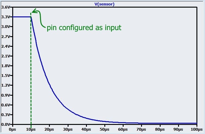
If someone touches the sensor and thereby creates an additional 3 pF of capacitance, the time constant will increase, as follows:
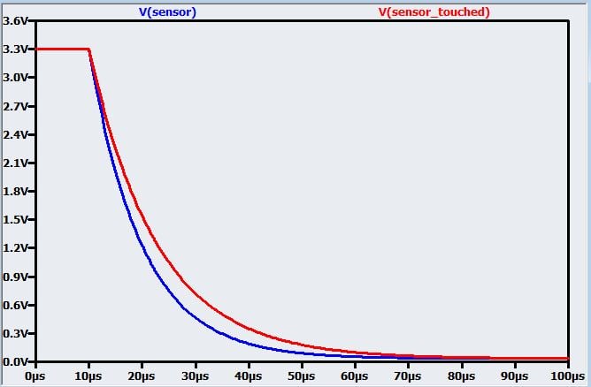
The discharge time is not much different by human standards, but a modern microcontroller could certainly detect this change. Let’s say we have a timer clocked at 25 MHz; we start the timer when we switch the pin to input mode. We can use this timer to track the discharge time by configuring the same pin to function as a trigger that initiates a capture event (“capturing” means storing the timer value in a separate register). The capture event will occur when the discharging voltage crosses the pin’s logic-low threshold, e.g., 0.6 V. As shown in the following plot, the difference in discharge time with a threshold of 0.6 V is ΔT = 5.2 µs.
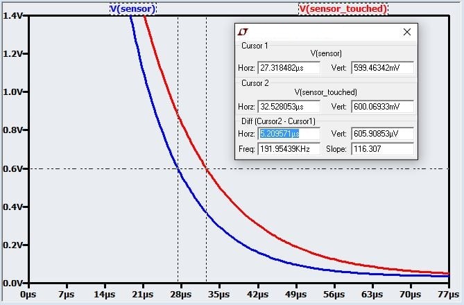
With a timer clock-source period of 1/(25 MHz) = 40 ns, this ΔT corresponds to 130 ticks. Even if the change in capacitance were reduced by a factor of 10, we would still have 13 ticks of difference between an untouched sensor and a touched sensor.
So the idea here is to repeatedly charge and discharge the capacitor while monitoring the discharge time; if the discharge time exceeds a predetermined threshold, the microcontroller assumes that a finger has come into “contact” with the touch-sensitive capacitor (I put “contact” in quotation marks because the finger never actually touches the capacitor—as mentioned in the previous article, the capacitor is separated from the external environment by solder mask and the device’s enclosure). However, real life is a little more complicated than the idealized discussion presented here; error sources are discussed below in the “Dealing with Reality” section.
Variable Capacitor, Variable Frequency
In the frequency-shift-based implementation, the capacitive sensor is used as the “C” portion of an RC oscillator, such that a change in capacitance causes a change in frequency. The output signal is used as the input to a counter module that counts the number of rising or falling edges that occur within a certain measurement period. When an approaching finger causes an increase in the capacitance of the sensor, the frequency of the oscillator’s output signal decreases, and thus the edge count also decreases.
The so-called relaxation oscillator is a common circuit that can be used for this purpose. It requires a few resistors and a comparator in addition to the touch-sensitive capacitor; this seems like a lot more trouble than the charge/discharge technique discussed above, but if your microcontroller has an integrated comparator module, it’s not too bad. I’m not going to go into detail on this oscillator circuit because 1) it is discussed elsewhere, including here and here, and 2) it seems unlikely that you would want to use the oscillator approach when there are many microcontrollers and discrete ICs that offer high-performance capacitive-touch-sense functionality. If you have no choice but to create your own capacitive-touch-sensing circuit, I think that the charge/discharge technique discussed above is more straightforward. Otherwise, make your life a little simpler by choosing a microcontroller with dedicated cap-sense hardware.
The capacitive-sense peripheral in the EFM32 microcontrollers from Silicon Labs is an example of an integrated module based on the relaxation-oscillator approach:
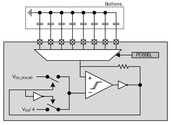
The multiplexer allows the oscillation frequency to be controlled by eight different touch-sensitive capacitors. By quickly cycling through the channels, the chip can effectively monitor eight touch-sensitive buttons simultaneously, because the microcontroller’s operating frequency is so high relative to the speed at which a finger moves.
Dealing with Reality
A capacitive-touch-sense system will be afflicted by both high-frequency and low-frequency noise.
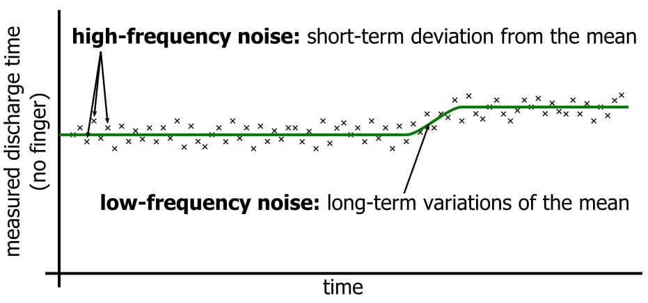
The high-frequency noise causes minor sample-to-sample variations in the measured discharge time or edge count. For example, the fingerless charge/discharge circuit discussed above might have a discharge time of 675 ticks, then 685 ticks, then 665 ticks, then 670 ticks, and so forth. The significance of this noise depends on the expected finger-induced change in discharge time. If the capacitance increases by 30%, the ΔT will be 130 ticks. If our high-frequency variation is only about ±10 ticks, we can easily distinguish signal from noise.
However, a 30% increase in capacitance is probably near the maximum amount of change that we could reasonably expect. If we get only a 3% change, the ΔT is 13 ticks, which is too close to the noise floor. One way to reduce the effect of noise is to increase the magnitude of the signal, and you can do this by reducing the physical separation between the PCB capacitor and the finger. Often, though, the mechanical design is constrained by other factors, so you have to make the best of whatever signal magnitude you get. In this case, you need to lower the noise floor, which can be accomplished by averaging. For example, each new discharge time could be compared not to the previous discharge time but to the mean of the last 4 or 8 or 32 discharge times. The frequency-shift technique discussed above automatically incorporates averaging because small variations around the mean frequency will not significantly affect the number of cycles counted within a measurement period that is long relative to the oscillation period.
Low-frequency noise refers to long-term variations in the fingerless sensor capacitance; these can be caused by environmental conditions. This sort of noise cannot be averaged out because the variation could persist for a very long period of time. Thus, the only way to effectively deal with low-frequency noise is to be adaptable: The threshold used to identify the presence of a finger can’t be a fixed value. Instead, it should be regularly adjusted based on measured values that do not exhibit significant short-term variations, such as those caused by the approach of a finger.
Conclusion
The implementation techniques discussed in this article demonstrate that capacitive touch sensing does not require complex hardware or highly sophisticated firmware. It is nonetheless a versatile, robust technology that can provide major performance improvements over mechanical alternatives.
Related Content