 Facebook
 Google
 GitHub
 Linkedin
Capacitive Touch Sensing with an EFM8 Microcontroller
This project explores capacitive-touch-sense technology using an evaluation board for an EFM8 Sleepy Bee microcontroller.
This project explores capacitive-touch-sense technology using an evaluation board for an EFM8 Sleepy Bee microcontroller.
Related Information
- Controlling an LCD via SPI: An Introduction to Project Development with an EFM8 Microcontroller
- Ambient Light Monitor: Display Measurements on an LCD
- Introduction to Capacitive Touch Sensing
- Circuits and Techniques for Implementing Capacitive Touch Sensing
Required Hardware/Software
The Dev Board
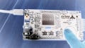
In addition to a microcontroller that has an integrated capacitive-sense module, the SLSTK2010A evaluation board has a PCB structure that can function as a capacitive-touch interface. You can see it in the bottom-right portion of the board:

There are actually four sensors here. The interior of the circle is an individual sensor. The area between the smaller circle and the larger circle is actually three sensors that interact in such a way as to form a circular slider, i.e., the signals from the three sensors can be processed so as to identify the location of a finger press. In the next photo you can (sort of) see the specialized interlocking sensor shape that makes this functionality possible, and then the sensor design is much more clearly indicated in the diagram that follows.


Graphic courtesy of Mark Hughes.
We have no need for the circular-slider capability in this article; nonetheless, we will be using one of the circular-slider sensors. Why, you ask? Simple: The individual sensor corresponding to the smaller circle is not connected to the microcontroller by default, and the only way to obtain said connection is via a zero-ohm resistor footprint that is slightly larger than a grain of sand. Furthermore, said footprint is perilously close to other components, including the microcontroller. So instead of using my soldering iron to melt the EFM8 and foul up a nearby resistor or two, I decided to just use one of the other sensors.
Changing Capacitance
We’ll start by using one of the demo projects available in Simplicity Studio:

Download the program and then press somewhere on the circular slider, and the LCD will show a white octagon corresponding to the position of your finger.
Let’s use this program to see what exactly is going on with the cap-sense signal. If you’re not familiar with capacitive-touch-sense technology, it’s a good idea to read the two cap-sense articles listed above in the “Related Information” section. If you don’t know much about capacitive sensing and you’re not in the mood for a technical article, here is the bottom line: A section of the PCB is designed so as to form a (usually fingertip-sized) capacitor. When your finger comes into contact with this PCB capacitor, the total capacitance increases. The PCB capacitor is incorporated into some sort of circuit that can detect this change in capacitance by analyzing variations in the timing characteristics of an applied signal.
I didn’t read every word in the cap-sense section of the Sleepy Bee reference manual, but it seems to me that there is no clear information on the specific capacitance-change-detecting technique used by the EFM8’s hardware. So let’s probe one of the cap-sense pins and see what is going on. I probed P0.2 and the LCD kindly tells me which section of the circular slider corresponds to the P0.2 signal (more on this later).
The scope reveals a periodic ramp waveform:

The following scope capture shows the width of the ramp pulse when I don’t have my finger anywhere near the P0.2 region of the circular slider.

The next scope capture shows you what the waveform looks like when I press firmly on the P0.2 sensor.

It might not be too obvious in the single-frame captures, but when I’m looking at the live display I can see clearly that contact with a finger causes a decrease in peak voltage and a change in the discharge portion of the ramp waveform. The change in the discharge characteristic is just what you would expect with increased capacitance: the decrease in voltage is slightly more gradual, and thus slightly more time is required for the voltage to return to 0 V.
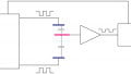
I didn’t see a significant change in frequency resulting from finger contact, so I can only assume that the Sleepy Bee’s “capacitance to digital converter” (as shown in the block diagram, below) is detecting changes in capacitance based on changes in the discharge portion of the ramp waveform, perhaps in conjunction with amplitude variations.

Block diagram for the capacitive-sense module, taken from the Sleepy Bee reference manual, page 154.
The Observer Effect
I would like to know a little more about the EFM8’s cap-sense measurements, but probing with an oscilloscope is not the best way to go about this. The reason should be clear from the little white octagon that appeared as soon as we probed the cap-sense signal—in this case the oscilloscope probe and input circuitry function as a rather bulky and expensive replacement for a fingertip. We can’t see the default state of the waveform because by applying the probe we are adding a relatively large amount of capacitance to the sensor.
So instead we need a real-time display that reports the capacitance measurements without interfering with the sensor. For this we will need the LCD and some custom firmware.
A Real-Time Capacitance Monitor
The plan here is to enable basic cap-sense functionality on the EFM8 and then display the capacitance measurements on the LCD. This will allow us to see the exact changes in measured capacitance that occur in response to any type of interaction between the sensor and a finger.
The majority of the firmware work involved in this project is related to the LCD interface—incorporating pixel-data arrays for the digits, writing pixel data to the LCD module, displaying a binary value as a base-ten number. I’m not going to say much about these topics because they are discussed in previous articles; this one is particularly relevant because the numeric display is similar to what I am doing in this project. The link toward the bottom of this article gives you access to all the source and project files, and you should be able to gather quite a bit of information by studying the code, which uses descriptive identifiers and is well commented.
One important difference that I’ll mention is the SPI interface. In previous projects I used interrupt-driven firmware for SPI communication between the EFM8 and the LCD module, but in this project I use a simpler polled implementation (remember the KISS principle).
Here is the pinout:

CS0: The Cap-Sense Controller
The Sleepy Bee’s cap-sense module is a high-performance peripheral that handles most of the details involved in measuring small variations in capacitance. It includes various features that I will probably never use or even pay attention to, but I’m sure they’re valuable for people who design consumer electronics products.
One feature that I really like is the integrated accumulate-and-average functionality. Capacitive-sense measurements can be noisy, so it’s handy that the EFM8 cap-sense hardware can automatically accumulate and average as many as 64 samples.
When you enable the “Capacitive Sensing Library” in the hardware configurator, you will notice that the IDE automatically inserts two cap-sense-related functions into your main() routine. I don’t know what these do, and to be honest I have limited patience for autopilot-style library code that only leaves me more oblivious to what is actually going on inside my microcontroller. So I deleted these function calls and configured the CS0 module manually. (Just to be fair, I certainly do appreciate hardware-configuration tools that greatly reduce the complicated and error-prone process of setting and clearing all the right bits in numerous special function registers.)
Here is the main() function:
int main(void)
{
	//call hardware initialization routine
	enter_DefaultMode_from_RESET();

	//give the EFM8 control over the LCD module
	EFM_DISP_ENABLE = HIGH;

	//initialize chip select to LOW (inactive)
	SPI_CS = LOW;

	//clear the LCD screen
	LCD_Clear_All();

	SFRPAGE = CAPSENSE_PAGE;

	//enable the cap-sense module
	CS0CN0_CSEN = TRUE;

	//select 16-bit conversions
	CS0MD2 &= ~(BIT7|BIT6);
	CS0MD2 |= (BIT7|BIT6);

	//make sure that the end-of-measurement interrupt flag is cleared
	CS0CN0_CSINT = CLEARED;

	while(1)
	{
		//initiate a capacitance measurement
		CS0CN0_CSBUSY = TRUE;
		while(!CS0CN0_CSINT); CS0CN0_CSINT = CLEARED;

		//print the measured value on the LCD
		Update_LCD(CS0D);

		Delay_10ms(10);
	}
}
The accumulation setting that I want is 64 samples, but I don't have to manually perform that configuration step because the accumulation setting is carried over from the option I selected in the hardware configurator tool. Also, the default start-of-measurement action is writing a 1 to CSBUSY (bit 4 in the CS0CN0 register), so I didn’t have to configure this either because CSBUSY is how I want to initiate measurements. I set the gain to 4x (the default is 8x) because, with the gain at 8x, it seemed like I was reaching or approaching the maximum measurement value when I pressed very firmly on the sensor; the gain, like the accumulation setting, can be selected via the hardware configurator.
As you can see from the Update_LCD(CS0D) statement, the number displayed on the screen is just the raw value from the cap-sense module’s data register. It’s not the measured capacitance in picofarads or any other unit, and furthermore the absolute capacitance is irrelevant—capacitive-sense technology is based on changes in capacitance.
The Firmware in Action
You can download the code here:
Here’s one little detail that might save you some trouble: When I was first testing the LCD interface, I noticed seemingly random display glitches. I eventually figured out that the debugger was interfering with the SPI communications, because the problem occurred only when I was running the program as part of a debug session. When I closed the connection between Simplicity Studio and the microcontroller and let the EFM8 program run independently, everything was fine.
You can see in the video below that a finger press creates a large change in measured capacitance—much larger than the noise variations, which are only a few counts when the finger is nowhere near the sensor. This demonstrates how effectively you could detect a finger press simply by choosing an appropriate threshold.
Conclusion
We now know a good deal about 1) how the Sleepy Bee’s cap-sense module detects changes in capacitance and 2) how to enable the module and perform basic measurements. We’ll continue to work with this evaluation board’s capacitive-touch-sense functionality in future articles.
Give this project a try for yourself! Get the BOM.
Related Content


Hi,
I want to control LED0 brightness by PWM, with touch sensing, not by joystick. i mean when i approach the ginger the led brightness increases. have you an example please?
Thank you in advance