Facebook
 Google
 GitHub
 Linkedin
Controlling an LCD via SPI: An Introduction to Project Development with an EFM8 Microcontroller
A simple LCD control project with an EFM8 evaluation board demonstrates basic principles of embedded development.
Microcontroller-based embedded designs begin with hardware, then move from low- to higher-level firmware development. We will explore this design process in the context of a simple program that uses a SiLabs EFM8 microcontroller to display a scrolling horizontal line on a 128-by-128-pixel LCD.
Previous Articles in This Series
Required Hardware/Software
-
Simplicity Studio integrated development environment
A Few Words on Working with Microcontrollers
In general, a microcontroller project can be discussed in terms of four interconnected functional blocks: port input/output, peripherals, firmware, and external components. The lowest level is represented by the port I/O configuration, which ensures that the port pins properly handle the actual voltage signals that serve as outputs from or inputs to the microcontroller. Peripherals (such as timers or serial communication modules) are a sort of intermediary between the port I/O and firmware: peripherals both process I/O signals from or to the port pins and initiate events that influence firmware execution. Firmware is the collection of instructions that governs the overall operation of the device; firmware can interface directly with port pins, but often the firmware interacts with peripherals, which reduce burden on the processor by independently accomplishing low-level hardware tasks. Finally, these three blocks—port I/O, peripherals, and firmware—work together to successfully interface with other components in the system.
Hardware and implementation details differ from one microcontroller to another, so there is a familiarization process involved when you start to develop projects with a new device. A well-written, well-illustrated data sheet is immensely helpful here, as is thoroughly commented sample code. But in the end, you need firsthand experience (along with plenty of patience when things don’t initially work) to become comfortable with the idiosyncrasies of a new microcontroller.
Fortunately, integrated configuration tools make this familiarization process quicker and less painful. Simplicity Studio includes a highly developed hardware configuration tool that greatly reduces the time and effort needed to properly configure the various registers that govern the operation of the device’s processor core, clock sources, power supply, port pins, and peripherals.
Project Overview
The objective is to display a scrolling horizontal line on a 128-by-128-pixel LCD module. This rather unexciting functionality serves as a convenient way to explore fundamental aspects of implementing projects with the EFM8 via Simplicity Studio. Configuring a microcontroller’s hardware can be a rather intricate process, and this article cannot cover all the concepts and techniques involved. Nonetheless, we will try to highlight some key implementation details, and then future articles will focus more on higher-level functionality.
Port I/O
First we need to assign port pins to the appropriate peripherals and configure pins as outputs where necessary. You may find that the basic task of choosing the input/output status of a pin is more complicated than expected—it’s not as simple as setting a configuration bit to 1 for input and 0 for output. Thus, it’s important to understand what is really going on with these pins:

This diagram represents a port pin’s input/output circuitry. The transistor labeled “WEAK” functions as a high-value resistor (about 200 kΩ). When the pin is set to “push-pull” mode, the output is connected directly to VDD or ground through one of the output transistors. Thus, the pin “drives” a logic low or logic high, so in this mode the pin is an output. If not in push-pull mode, the pin is in “open-drain” mode. This means that the upper drive transistor (not the one labeled “WEAK”) is disabled. Here is an important point: you cannot call this “input mode” because the pin can still drive logic low through the lower transistor. The pin is a true input only if you configure it as open-drain and write a 1 to the corresponding bit in the port pin latch register. Now both drive transistors are disabled and the pin is pulled up to VDD through the “weak” pull-up transistor. This arrangement is necessary because sometimes (for example, with the I2C serial bus) a pin must be able to operate in open-drain mode as both an input and an output.
Upon reset, all the port pins default to input mode, so we can just configure a few pins for output mode and leave the rest alone. First, though, we need to assign the peripherals so we know which pins should be outputs. SiLabs microcontrollers connect peripherals with port pins through something called a crossbar, which is a somewhat confusing but also highly versatile architecture. For this project, the only peripheral that needs port pins is the SPI bus.

SPI_SCK (serial clock) and SPI_MOSI (master-out-slave-in) must be configured as push-pull outputs; SPI_MISO (master-in-slave-out) is not used in this project. We must also set P0.1 to push-pull because this pin is used as the slave select signal (see the SPI discussion below). Note that P0.0 to P0.5 must all be “skipped” in the crossbar configuration to ensure that the SPI signals appear on the pins that are routed to the LCD serial interface pins.
Peripherals
This project uses three peripherals: SPI0, Timer2, and Timer4.

In the above image, the watchdog timer is checked only because it is disabled as part of the hardware configuration process. SPI is a fairly straightforward serial communication interface capable of full-duplex communication between a “master” and one or more “slaves.”

The slave select signal (NSS in the above diagram) generated by the SPI peripheral is not compatible with the LCD interface, which is why we have to send this signal manually via P0.1.
Timer2 is used to set the frame rate by initiating an LCD update when it overflows. The LCD data sheet recommends a frame frequency between 54 and 65 Hz, so we have configured Timer2 to overflow after 16.665 ms, which corresponds to 60 Hz:

Timer4 is used to implement short delays required by the LCD’s serial interface. The clock source is configured so that one Timer4 count is approximately 0.33 μs.
Interrupts
An interrupt is a hardware-driven signal that causes the processor to execute a particular section of code. Interrupts are the primary means by which a microcontroller’s firmware responds to important events, both internal (such as a timer overflow) and external (such as a low-to-high voltage transition on a port pin). In this project, interrupts generated by Timer2 are used to schedule LCD updates according to the predetermined frame rate, and SPI0 interrupts govern the code that handles serial communication with the LCD.

Firmware
Fortunately, code required to configure the microcontroller and set up interrupt service routines is automatically generated by the hardware configuration tool. The remaining code is mostly the following: the SPI state machine in Interrupts.c, LCD data and address handling in LCD.c, and the infinite loop that initiates LCD write events in SPI_Test_main.c. You can download all the project and source files at the bottom of this page. The code is written using informative variable names and contains many explanatory comments, so it should greatly help you to understand the details of the firmware used in this project.
This flowchart clarifies the functionality of the state machine that controls SPI transfers:
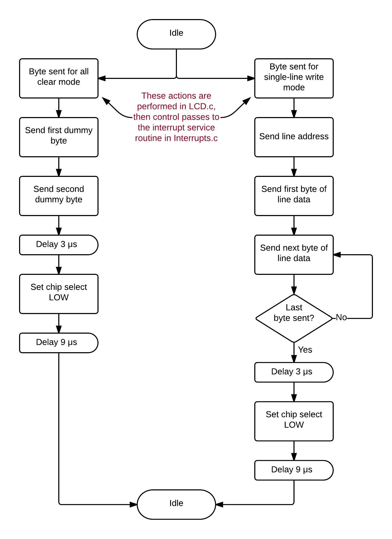
The following timing diagram for “all clear mode” illustrates the general characteristics of the serial interface between the microcontroller and the LCD. For other modes, refer to the LCD module’s datasheet.

The LCD is arranged as 128 horizontal lines of 128 pixels each. To form a horizontal black line across the display, we clear all the pixels to white then write all zeros to one line address. To create the scrolling effect, we update the display as follows:
- Timer2 overflows, causing an interrupt. Write the first line to all black.
- Timer2 overflows again. Write that same line to all white, then increment the line address.
- Timer2 overflows, and we write the new line to all black, then another overflow and we clear the new line.
- This continues until we reach the last line, at which point the process starts over with the address of the first line.
Video
Next Article in Series: Displaying Characters on an LCD with an EFM8 Microcontroller
Give this project a try for yourself! Get the BOM.