Facebook
 Google
 GitHub
 Linkedin
Circular Touch Sensing with an EFM8 Microcontroller
In this project we will develop an algorithm for precisely locating a touch event that occurs somewhere on a circular capacitive sensor.
In this project we will develop an algorithm for precisely locating a touch event that occurs somewhere on a circular capacitive sensor.
Related Information
- Controlling an LCD via SPI: An Introduction to Project Development with an EFM8 Microcontroller
- Ambient Light Monitor: Display Measurements on an LCD
- Introduction to Capacitive Touch Sensing
- Circuits and Techniques for Implementing Capacitive Touch Sensing
Required Hardware/Software
The Circular Sensor
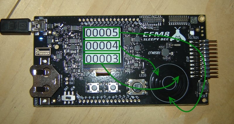
The SLSTK2010A evaluation board includes, among other things, an EFM8 Sleepy Bee microcontroller and a circular capacitive sensor. It is possible to perform capacitive touch sensing using any microcontroller, but you’ll get better results with a specialized hardware module designed by experts, and that is exactly what is integrated into the Sleepy Bee. A previous article, entitled Capacitive Touch Sensing with an EFM8 Microcontroller, explores the functionality of this peripheral, which is referred to as CS0 (Capacitive Sense 0) in the EFM8 Sleepy Bee reference manual.
The circular capacitive sensor provides a non-three-dimensional-torus–shaped (or, if you prefer, donut-shaped) region in which user input can be received via the application of a fingertip. There are real-world constraints that limit the number of separate touch positions that can be accurately identified, but overall I would say that the resolution is quite good—my guess is that carefully designed firmware could reliably distinguish 5° increments, which means that the circular sensor might offer as many as 72 separate user-input positions.
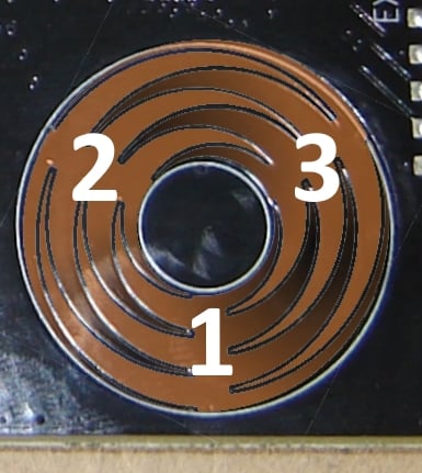
This is fairly impressive, but it becomes even more impressive when you consider that these 72 separate positions are achieved with only three capacitive-sense channels. These three channels, however, can provide this functionality only because they are connected to three very cleverly designed capacitive PCB sensors, as shown in the following photo and diagram.
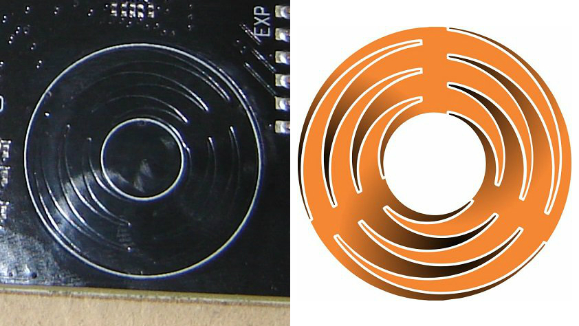
Graphic courtesy of Mark Hughes.
The central portion of each sensor corresponds to the radial section between the tips of the curving protrusions. When you touch the central portion, the change in capacitance (aka “cap delta”) for that sensor will be highest, and the cap delta will decrease steadily as the fingertip moves away from the central portion in either direction.
As you can see, though, as you move away from one central portion, you are moving toward another. This means that the decreasing cap delta on the first channel occurs in conjunction with an increasing cap delta on the other channel. By combining the cap-delta measurements from adjacent sensors, we can calculate an approximate angular position for any touch event that occurs somewhere on the torus.
Before we move on, let’s briefly discuss why this circular slider is so nifty in the context of modern electronics. After all, we need some fairly complicated firmware to get decent angular positioning using only three sensors. Why not just use a dozen ordinary round sensors spaced evenly around the circle?
Well, each sensor needs a pin on the microcontroller, so now you have consumed 12 pins and in the process you’ve significantly decreased your resolution. Firmware is cheap and doesn’t take up any space, whereas microcontroller pins (and the PCB traces connected to them) take up a lot of space relative to the miniscule devices that engineers are now expected to design. And in the long term hardware is expensive, at least compared to firmware. Fewer pins, smaller ICs, less hardware, more firmware—this is the current paradigm, at least for consumer electronics.
Keeping Track of Our Sensors
The following diagram indicates how the sensor numbers used in the code correspond to the physical arrangement.
Again, these are the “sensor numbers”—i.e., arbitrary identifiers assigned to the three physical sensors. These numbers are not the same as the “channel”—i.e., which internal cap-sense channel is connected to the physical sensor. And of course the channel number does not necessarily correspond in an intuitive way to the external pin to which the sensor is electrically connected. Here is the mapping:
| Sensor Number | Channel | Pin | Location |
|---|---|---|---|
| 1 | 2 | P0.2 | bottom-middle |
| 2 | 3 | P0.3 | top-left |
| 3 | 13 | P1.5 | top-right |
Establishing a Baseline
The first thing we need to do is set a certain value as the official “unpressed” capacitance of a particular sensor. This step is critical—first, because capacitive touch sensing revolves around changes in capacitance, not absolute capacitance, and second, because the three sensors can exhibit large variations in unpressed capacitance. For example, I just plugged in my board, and at the moment the three (seemingly identical) sensors have unpressed capacitance values of approximately 15700 counts, 14800 counts, and 14150 counts.
I establish unpressed capacitance values as follows:
Accumulated_Capacitance_Sensor1 = 0;
Accumulated_Capacitance_Sensor2 = 0;
Accumulated_Capacitance_Sensor3 = 0;

for (n = 0; n < 16; n++)
{
	Accumulated_Capacitance_Sensor1 += Measure_Capacitance(SENSOR_1);
	Delay_us(1000);
	Accumulated_Capacitance_Sensor2 += Measure_Capacitance(SENSOR_2);
	Delay_us(1000);
	Accumulated_Capacitance_Sensor3 += Measure_Capacitance(SENSOR_3);
	Delay_10ms(5); Delay_us(6000);
}

Sensor1_Unpressed = (Accumulated_Capacitance_Sensor1 >> 4);
Sensor2_Unpressed = (Accumulated_Capacitance_Sensor2 >> 4);
Sensor3_Unpressed = (Accumulated_Capacitance_Sensor3 >> 4);
You can see here that I’m doing a lot of averaging. The CS0 hardware is configured to average 64 samples per measurement, then I’m averaging 16 of these already-averaged measurements. Maybe this is overkill, but all of the cap-sense functionality is based on these unpressed values, so I want to make sure that they don’t get corrupted by transient noise sources or some sort of measurement glitch.
Note: It’s important to avoid major differences between these initial unpressed measurements and however you sample the cap-sense channels during normal operation. I’m specifically referring to maintaining the channel sequence and ensuring similar intervals between measurements. For example, if during normal operation you sample sensor 1, then sensor 2, then sensor 3, with 1 ms between each measurement, you don’t want to determine your unpressed values by taking 16 rapid-fire sensor 1 measurements, then immediately taking 16 rapid-fire sensor 2 measurements, then immediately taking 16 rapid-fire sensor 3 measurements. This would lead to small but noticeable discrepancies between normal-operation measurements and establishing-unpressed-capacitance measurements, such that your official unpressed values will be different from the actual typical unpressed values observed during normal program operation.
Detecting a Press
Before calculating an angular position, we need to recognize that a fingertip is in contact with the circular sensor. We do this by scanning the channels, calculating the cap delta, and comparing it to a threshold.
Sensor1_Measurement = Measure_Capacitance(SENSOR_1);
Sensor1_Delta = Sensor1_Measurement - Sensor1_Unpressed;
if(Sensor1_Delta < 0)
	Sensor1_Delta = 0;
Delay_us(1000);

Sensor2_Measurement = Measure_Capacitance(SENSOR_2);
Sensor2_Delta = Sensor2_Measurement - Sensor2_Unpressed;
if(Sensor2_Delta < 0)
	Sensor2_Delta = 0;
Delay_us(1000);

Sensor3_Measurement = Measure_Capacitance(SENSOR_3);
Sensor3_Delta = Sensor3_Measurement - Sensor3_Unpressed;
if(Sensor3_Delta < 0)
	Sensor3_Delta = 0;

if(Sensor1_Delta > TOUCH_DELTA_THRESHOLD
		|| Sensor2_Delta > TOUCH_DELTA_THRESHOLD
		|| Sensor3_Delta > TOUCH_DELTA_THRESHOLD)
{
        ...
Through experimentation I found that the minimum increase in capacitance from a not-very-firm finger press was about 6000 counts (I have the cap-sense gain set to 4x). I did this by touching halfway between two sensors; this leads to the minimum single-sensor increase in capacitance because the total increase is shared equally between two sensors.
So we can assume that a fingertip coming into contact with any portion of the circular sensor will lead to a cap delta of at least 6000 counts. Based on this you might use 4000 or 5000 counts as a cap-delta threshold, but I chose 2000, simply because 2000 is still far above the typical noise amplitude and will give us higher sensitivity (maybe some fingers have less capacitance than others . . .).
Next, we simply compare each sensor’s cap delta to the threshold, and if at least one exceeds the threshold, we continue processing sensor data in order to determine the angular position of the touch event.
Calculating Position
Before I go any further, I should mention the following: The angular-position algorithm that I developed might be far from optimal. But that’s not the point. The point is, this algorithm is the result of a commonsense thought process that reflects the “intuitive path” from intention, through consideration and observation and analysis, to implementation. I prefer to begin with this intuitive path, because it will reliably lead to deeper understanding of the issue at hand, and it is a good idea to seek this deeper understanding before looking around for a potentially better implementation created by someone else.
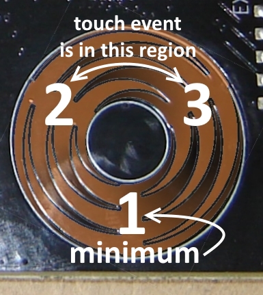
I first identify the 120°-segment in which the touch event is taking place; this is done by looking for the sensor with the lowest measurement. For example, if sensor 1 has the lowest measurement, the fingertip is between sensors 2 and 3.
if(Sensor1_Delta > TOUCH_DELTA_THRESHOLD
		|| Sensor2_Delta > TOUCH_DELTA_THRESHOLD
		|| Sensor3_Delta > TOUCH_DELTA_THRESHOLD)
{
	switch(Find_Minimum(Sensor1_Delta, Sensor2_Delta, Sensor3_Delta))
	{
		case SENSOR_1: Segment = UPPER_MIDDLE;
		break;

		case SENSOR_2: Segment = LOWER_RIGHT;
		break;

		case SENSOR_3: Segment = LOWER_LEFT;
		break;
	}

        ...
The key to the next portion of the algorithm is the assumption that the total increase in capacitance is the same regardless of the angular position. Let’s say that the finger is on the center of sensor 2 and produces an increase of 15000 counts from sensor 2 and an increase of zero counts from sensor 3. Under this assumption, both sensor 2 and sensor 3 will have an increase of 7500 counts if the touch event is halfway between the two. I don’t know how accurate this assumption is, but the general idea seems to be valid enough to produce good results.
Next, we simply divide the sensor 2 (or sensor 3 or sensor 1) delta by the total delta, and then we multiply this ratio by 120°. Finally, we add this angle to the angle corresponding to the “beginning” of the 120°-segment.
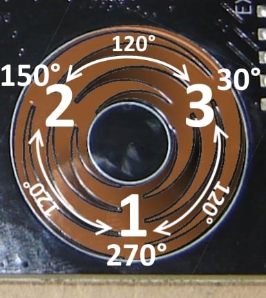
The main weakness with this technique is the following: The angles near the center of the sensors (i.e., 30°, 150°, 270°) get “skipped” because the cap delta doesn’t go all the way to zero—for example, if your fingertip is right on the center of sensor 3, the sensor 2 reading might be 400 counts instead of zero counts. The result is that the ratio of sensor 2 delta to total delta will not extend all the way from 0% to 100%. To correct for this, I assume (based on observations) that the initially calculated ratio will extend from 5% to 95%, and then I map the ratio from the range 5–95 to the range 0–100. The mapping constants are determined by solving the following simultaneous equations:
$$\begin{cases} 0.05x+y=0 \\ 0.95x + y=1 \\ \end{cases}$$
I’m satisfied with the performance provided by this approach, but some additional fine-tuning would be needed to completely eliminate the “jumpy” measurements that occur at the 30°, 150°, and 270° transition regions.
if(Segment == UPPER_MIDDLE)
{
	TotalDelta = Sensor2_Delta + Sensor3_Delta;

	Ratio = (float)Sensor2_Delta/TotalDelta;
	Ratio = (Ratio*1.1111) - 0.05556;

	AngularPosition = (Ratio*120) + 30;
}

else if(Segment == LOWER_RIGHT)
{
	TotalDelta = Sensor3_Delta + Sensor1_Delta;

	Ratio = (float)Sensor3_Delta/TotalDelta;
	Ratio = (Ratio*1.1111) - 0.05556;

	AngularPosition = (Ratio*120) + 270;

	if(AngularPosition >= 360)
		AngularPosition = AngularPosition - 360;
}

else if(Segment == LOWER_LEFT)
{
	TotalDelta = Sensor2_Delta + Sensor1_Delta;

	Ratio = (float)Sensor1_Delta/TotalDelta;
	Ratio = (Ratio*1.1111) - 0.05556;

	AngularPosition = (Ratio*120) + 150;
}
Conclusion
You can use the following link to download all the source and project files.
EFM8_CapacitiveCircularSense.zip
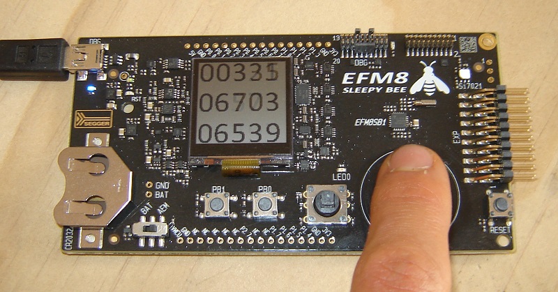
As shown in the video below, the program has two modes: In the default mode, it displays the angular position of the current or most recent touch event. In the second mode, it displays the cap delta for each channel.
In a future article we will incorporate this angular-position functionality into a circular-touch-sensor-based user interface.
Give this project a try for yourself! Get the BOM.