
 Facebook
 Google
 GitHub
 Linkedin
Using the Arduino Uno Q to Build a DDS Sine Wave Generator
In this project, we'll construct and test a microcontroller-based system that digitally generates analog signals.
As its name suggests, direct digital synthesis (DDS) is a technique for digitally generating analog waveforms. It is highly useful in applications where quickly generating waveforms across a range of frequencies is necessary. Spectrum analyzers and software-defined radios (SDRs), for example, both rely on DDS techniques.
In this article, we'll use an Arduino Uno Q to implement a DDS sine wave generator. At the end of the article, we'll test whether it works by hooking it up to a speaker.
The basic architecture of a DDS circuit is shown in Figure 1. We'll use this diagram as a model when building our sine wave generator.
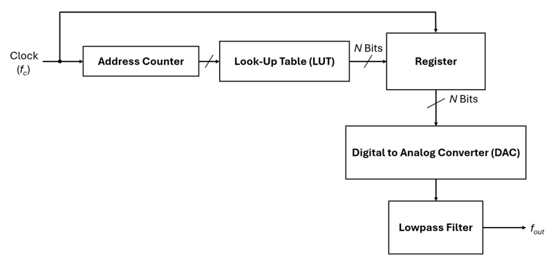
Figure 1. DDS concept diagram.
The look-up table (LUT) stores the sine wave's data points. A stable clock with an established frequency (fc) drives an address counter. As the address counter increments, a new digital sample of the sine wave is transferred from the LUT to the register. The DAC converts the digital sample to an analog output value. This output is then passed through a lowpass filter.
Since the DDS process is continuous, this produces a fully represented sine wave. If we wanted to create a square or triangle wave, we could use a different LUT.
The calculations for a DDS system's output frequency are quite basic. The LUT stores N samples of a single sinusoidal waveform. The DAC progresses through these N samples to generate a sine wave. Therefore, the output frequency is given by the sample rate (fs) divided by the number of samples per cycle:
$$f_{out}~=~\frac{f_s}{N}$$
Equation 1.
Since the DAC's sample frequency is typically fixed, we can use Equation 1 to calculate the number of samples in the waveform for a desired output frequency.
We will use an Arduino Uno Q to implement the LUT and data register. The DDS software algorithm builds the LUT using the algorithm in Figure 2.
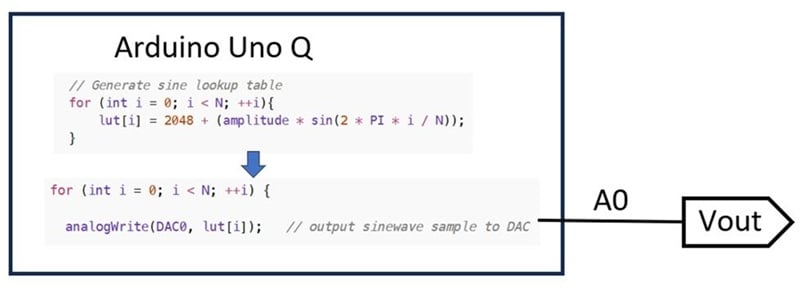
Figure 2. Uno Q software-implemented LUT.
Now that we've covered the basic waveform synthesis math, it's time to build the sine wave generator.
Building the DDS Sine Wave Generator
The concept of the DDS Sine Wave Generator is illustrated in Figure 3.

Figure 3. The DDS Sine Wave Generator project concept.
Building this project will require a few basic off-the-shelf components:
- Arduino Uno Q (2 GB or 4 GB).
- A 10 KΩ potentiometer (to act as the volume control).
- A small solderless breadboard.
The project schematic is shown in Figure 4.
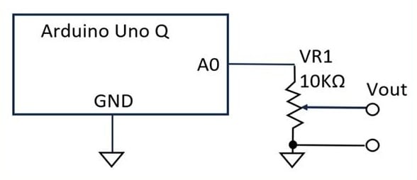
Figure 4. Schematic for building the DDS Sine Wave Generator project.
The solderless breadboard makes wiring the components quite easy. Figure 5 provides an additional reference for assembling the project.
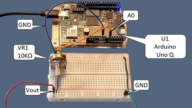
Figure 5. Assembly reference for the DDS Sine Wave Generator.
Once the physical assembly is complete, the next step is uploading the project code to the Arduino Uno Q using the Arduino Uno IDE. After that, you'll be ready to check whether the sine wave generator works.
Testing the Sine Wave Generator
First, we'll use an oscilloscope to observe the signal. The oscilloscope probe should be attached to the generator's Vout and GND test leads, as in Figure 6.
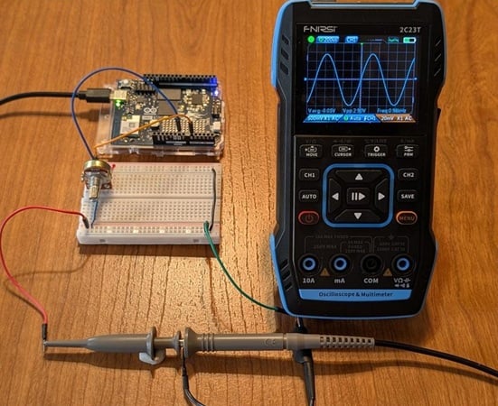
Figure 6. Testing the sine wave generator with an oscilloscope.
Figure 7 provides a closer view of the output signal.
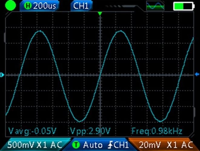
Figure 7. A close-up view of the output signal measured by the oscilloscope.
As we can see, the DDS software produces a 0.98 KHz frequency with a peak-to-peak voltage of 2.9 V.
Testing the Volume Control
As illustrated in Figure 7, the Uno Q's sine wave frequency is approximately 1 KHz. Hearing this tone requires a basic audio speaker, which we'll connect to the Arduino Uno Q as shown in Figure 8.
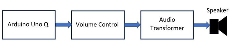
Figure 8. The sine wave generator, which is made up of the Uno Q and volume control, is connected to the speaker via an audio transformer.
As you can see in Figure 9, I chose to use an Elenco Electronic Playground project kit as my audio unit.
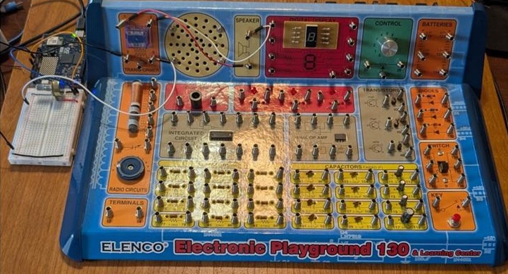
Figure 9. The DDS Sine Wave Generator connected to an Elenco Playground kit for audio output.
The kit includes a built-in audio transformer and 8 Ω speaker. The audio transformer's primary winding is attached to the 10 KΩ potentiometer's wiper pin and to ground. The secondary winding is wired across the 8 Ω speaker. The circuit diagram is shown in Figure 10.
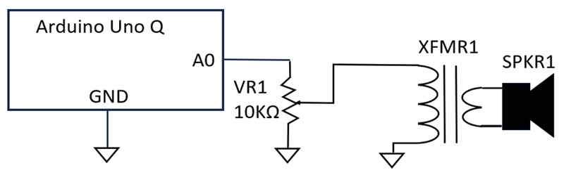
Figure 10. Circuit schematic for audio output testing.
The audio transformer provides an impedance match between the volume control (VR1) and the speaker. As the volume control is adjusted, we can hear changes in the amplitude. For a demonstration, watch the video clip in Figure 11 with the sound on.
Figure 11. The audio test setup in action.
If you want to increase the volume from the generator, I suggest using an LM386 audio power amplifier wired to the audio transformer speaker.
Featured image used courtesy of Arduino; all other images used courtesy of Don Wilcher
Related Content










I built something similar back in the 70’s with an Intel 4004, paper-tape/TTY and a light-pen to draw any arbitrary waveform on a small B&W monitor (master’s project) at relatively high cost. Now I use Raspberry Pi Uno at next to nothing cost for projects. How things have changed!
Does this project use something specific to Uno Q, or any Arduino would be the same?