 Facebook
 Google
 GitHub
 Linkedin
Digital Square Wave Generator Design Via a Ring Oscillator, 555 Timer, and Arduino
Learn about digital square wave generators using a ring oscillator, a 555 timer-based oscillator, and an Arduino-generated square wave oscillator.
Previously, we introduced the concept of designing square wave oscillators, namely operational amplifiers (op-amp) and transistor-based analog implementations of an astable multivibrator. In this article, we'll look into the digital methods to implement a square wave oscillator while discussing its advantages and limitations.
Before digging in, let's note that there are three examples that we'll analyze:
- A ring oscillator
- A 555 timer-based oscillator
- An Arduino to produce a square wave oscillator
Square Wave Generator Using a Ring Oscillator
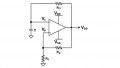
A ring oscillator has a fairly simple architecture that utilizes a string of inverters with the final output fed into the first input, creating a ring, as shown in Figure 1.
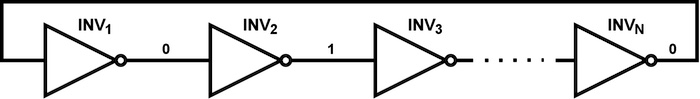
Figure 1. Generic ring oscillator architecture
Not only is the architecture simple, but so is the operation of this circuit. Upon startup, let’s assume that INV1 goes from logic 0 to logic 1. As the output of this inverter begins to rise, once the trip point of INV2 is hit, that output will begin to decrease to logic 0. This chain reaction continues to the final inverter, INVN, and that output then feeds back to the beginning to sustain the reaction. Overall, this reaction creates constant oscillation, and assuming all inverters have the same rise/fall times, a square wave output will be generated.
For the circuit to operate as described, the number of inverters in the ring (represented by N in Figure 1) must be odd. This requirement is necessary because, as we see in Figure 1, the output of any inverter, INVX, where X is even, will have an output that complements the output of INV1. If this value is fed back to INV1, there will be no change and, thus, no oscillation. While in this simple example, we use only inverters, you can use any logic gate throughout this circuit. However, in this ring example, there must be an odd number of inverting stages to oscillate.
Now, a question you might ask is: what aspects of the circuit decide the operating frequency? Basically, the inherent delay of each inverter (td), and the number of stages (N) decide this according to the equation:
$$f = \frac{1}{2t_dN}$$
Since td is usually small, and it is desirable to minimize N, the frequency is normally high, on the order of hundreds of MHz or even GHz. For lower-speed applications or for precise frequency control, users must typically add a load to the output of each inverter, most simply via an RC circuit, as shown in Figure 2.
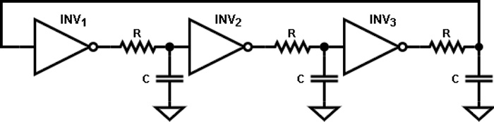
Figure 2. Ring oscillator with RC load
Moving forward, assuming all inverters trip at $$\frac{V_{DD}}{2}$$, where VDD is the supply voltage, the oscillating frequency becomes:
$$f = \frac{1}{2(t_d+0.69RC)N}$$
Next, assuming that RC > td, we can say that the oscillating frequency depends purely on the RC time constant and the number of stages.
As for advantages, the simplicity of this design makes it attractive for high-speed oscillator designs; however, for lower frequencies, it is hard to control these. Another drawback is that this architecture is generally power-consuming due to the high switching rates.
Using a 555 Timer as a Square Wave Generator
Next, we will discuss creating a square wave oscillator using a 555 timer. This general-purpose IC is used for:
- Various pulse generation
- Delay
- Timing
- Oscillator applications
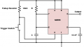
There are many varieties of 555 timers created by several companies, but we will focus on the LM555 from Texas Instruments. Section 7.4.2 of the datasheet illustrates the astable operation of the timer, which, as we know from the previous article, is what we are interested in. The schematic to implement is shown in Figure 3.
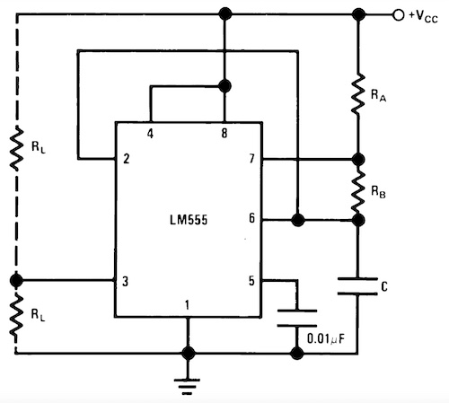
Figure 3. LM555 timer setup for astable operation mode. Image used courtesy of Texas Instruments
Here, the capacitor, C, is charged by the resistors, RA and RB. Once it hits the upper trip point (in the case of the timer, ⅔ of VCC), C then discharges down to ⅓ of VCC through RB. At this point, the capacitor begins to charge again, and this behavior continues indefinitely. From this, we can obtain the charge and discharge times and the period of oscillation via the equations below:
$$t_{rise}=0.69(R_A+R_B)C$$
$$t_{fall}=0.69R_BC$$
$$T=t_{rise}+t_{fall}$$
$$f=\frac{1}{T}=\frac{1.44}{(R_A+2R_B)C}$$
Here, we can see that not only do we have control of the oscillation frequency but also the output duty cycle. However, these cannot be shorter than tfall, which means that the duty cycle must be greater than 50% but can approach a square wave duty cycle if RB > RA.
The advantages of this implementation are that it is simple, requires minimal hardware, and is also a stable and reliable solution for low-speed oscillators. As for limitations, this design isn't applicable for duty cycles less than 50% are required or if high speeds are needed.
An Arduino-based Square Wave Generator Using an Arduino UNO R3
Lastly, we will discuss implementing an oscillator via an Arduino. For our example, we will look at the Arduino UNO R3. The pinout for this board is shown in Figure 4.
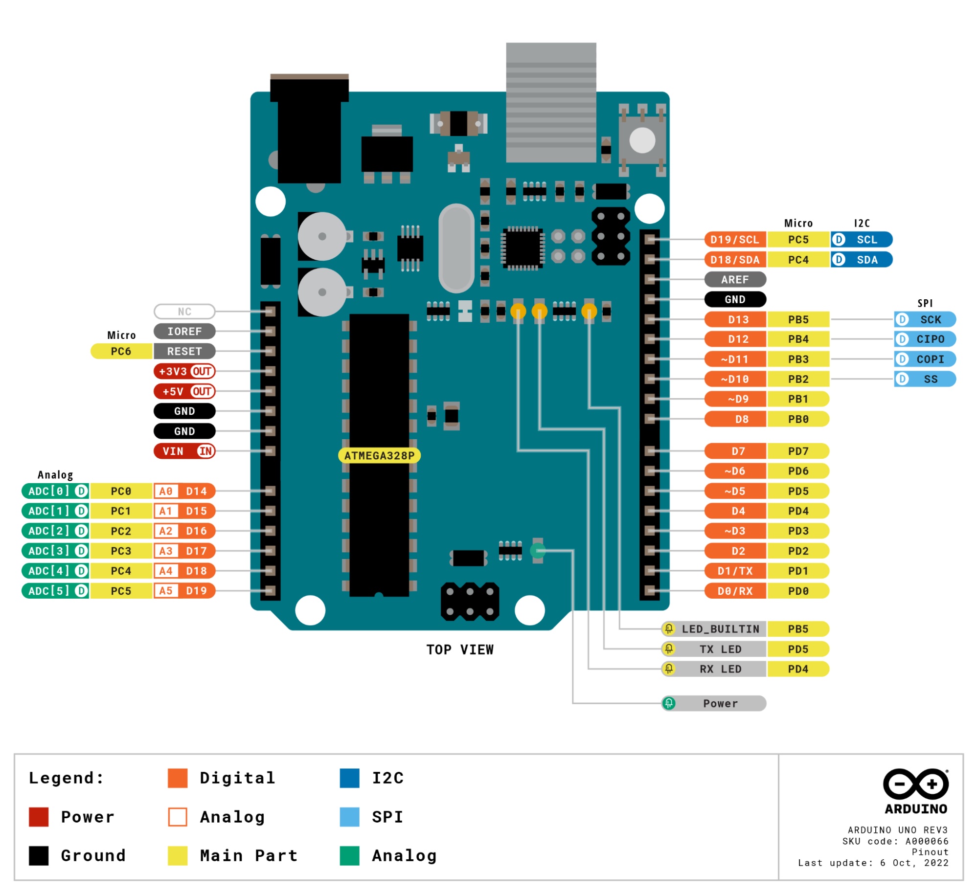
Figure 4. Arduino UNO R3 pinout. Image used courtesy of Arduino [Click image to enlarge]
For our generator, we will utilize one of the Arduino UNO's digital I/O pins, specifically, D7. No external hardware will be required to implement this solution, as this can all be defined via the Arduino program shown below:
int freq = 100;     //Set the user-defined frequency value in Hz

int per_ms = 1e3*(1/freq); //Set time in one state (high or low) as T/2 in milliseconds

int dutyCyc = 0.5; //Set duty cycle of output waveform


void setup() {

  pinMode(7, OUTPUT); //Set D7 as a digital output

}


//Oscillating Loop

void loop() {

  digitalWrite(7, HIGH); //Set D7 to logic 1

  delay(dutyCyc*per_ms); //Leave at logic 1 for T/2

  digitalWrite(7, LOW); //Set D7 to logic 0

  delay((1-dutyCyc)*per_ms); //Leave at logic 0 for T/2

}
In the above code snippet, we have three global variables declared, allowing the user to set the frequency and duty cycle. In this example, we can create a 100 Hz output with a duty cycle of 50%, which results in a square wave. From there, we can then initialize our digital output pin within the void setup block using the "pinMode" function. Next, we can enter a continuous loop where we set D7 HIGH and leave the output at that value for a time equal to the duty cycle multiplied by the period. Finally, we can turn the output to logic LOW and leave the signal there for the remainder of the period. As a result, this loop will continue indefinitely once the Arduino is turned on.
As you can see, the software implementation allows for high flexibility with zero external hardware. While this is fairly simple, we are limited to the bandwidth of the Arduino unless we use an external oscillator to push for higher frequencies if a high-speed oscillator is required.


The 555 is closer to a square wave as Ra approaches zero. Typically Rb >> Ra if you want the high and low times roughly equal. . Or you could use a flip-flop to divide the frequency by 2 and get an exact square wave.