 Facebook
 Google
 GitHub
 Linkedin
Build an Arduino-LabVIEW Analog Voltmeter
This project will show how to build a basic analog voltmeter using an Arduino Uno, LabVIEW software, and littleBits electronics modules.
Introduction
Electrical testing and measurements is a fundamental topic taught in a community college DC electronics course. The idea behind teaching this topic is to introduce basic electrical instruments technology and measuring practices to Industrial Electrical-Electronics technology (ILT) students. The first electrical instrument introduced to ILT students is the multimeter. The multimeter is a basic electrical instrument used to measure electric circuit parameters such as voltage, current, and resistance. The multimeter is designed with analog meters or liquid crystal displays (LCDs) for displaying voltage, current, and resistance electric circuits values. The concept behind this project is to show how a simple analog voltmeter can be built using an Arduino, several littleBits electronic modules, LabView, and LINX software packages. After following the project build instructions, the analog voltmeter will be checked against a digital voltmeter for measurement accuracy using a littleBits slide dimmer control circuit.
Parts List
- Arduino Uno
- littleBits proto module
- littleBits mounting board
- littleBits slide dimmer
- LabView software
- LINX add-on software
- Jumper wires
- 3-digit digital panel meter
Installing the LabView software
National Instruments (NI) LabView software allows a variety of virtual instruments (VI), electronic controllers, and robotics devices to be built using a graphical programming language. By placing controls on a user-form and wiring a block diagram with embedded functions, you can easily build a graphical user interface (GUI) for controlling electronics and robotics devices. The first step in making the analog voltmeter is to download the LabView software.

The MakerHub website to obtain LabView software for building an analog voltmeter
There are several software options to choose from, which is convenient from a project development cost view point. Install the software to your desktop PC or notebook book computer following the installation prompts. After the software has been installed on your target machine, the next project task is to include the LINX add on package.
Installing the LINX add-on package
The LINX add-on package allows a variety of embedded control development platforms like the Arduino Uno, Diligent's chipkit and NI myRIO to interface with electronic circuits, electromechanical components, and sensors easily using LabVIEW software. The LINX firmware allows communication between the interfacing components and the embedded control development platforms to communicate using USB, I2C (inter-integrated circuit), and SPI (serial peripheral interface) protocols. Also, analog, digital, and PWM (pulse width modulation) signals can easily be controlled using the LabVIEW VI based software as well. Download the LINX add-on software to your development machine’s hard-drive. Install the add-on software package following the installation prompts.
The LabVIEW MakerHub LINX add on software package allows direct communication and control of the embedded control development platforms’ I/O (input/output) pins interfaced to electronic circuits, sensors, and electromechanical actuators.
Loading the LINX Firmware
To complete the final installation phase of the LINX project task, the following steps will assist in loading the firmware to your target embedded control development platform. For this project, the Arduino Uno is used.
- Attach the Arduino Uno to your desktop PC or notebook using a USB cable.
- Launch LabVIEW software.
- Click Tools>> MakerHub>>LINX>> Firmware Wizard.
- Select the COM Port associated with your device and click Next.
- Select the Firmware Version (start with the Serial/USB firmware) and click Next. Note: The TX (transmit) and RX(receive) LEDs on your Arduino Uno should be on for a few seconds while the firmware is being installed. If not, repeat this step again.
Click Launch Example and follow the instructions on the front panel.
The next development phase of the project is to communicate with the LabVIEW analog voltmeter VI.
The LabVIEW Analog Voltmeter VI
The analog voltmeter VI is a modified version of the tutorials provided by LabVIEW MakerHub. The components to build the analog voltmeter consist of a littleBits slide dimmer control circuit, an Arduino Uno, and the LabVIEW analog voltmeter VI. The block diagram for the analog voltmeter project is shown next.

The LabVIEW software reduces the number of physical circuit components required to build an analog voltmeter.
The original VI consisted of a graph that displays a range of analog DC voltages applied to the Arduino Uno’s “A0” input pin. I changed the graph to a meter and added an HI limit LED and reference control to the GUI, shown as follows.

The original VI used an “x-y” graph to display the input voltage applied to the Arduino Uno. The x-y graph was replaced with an analog meter to make a virtual instrument DC voltmeter.
I’ve also added a Hi Limit LED along with a reference control to the original virtual instrument design. The reference control is used to set a threshold detection input voltage to be applied to the Arduino Uno’s A0 pin. If the input voltage exceeds the reference voltage, the Hi Limit LED will turn ON. The stop button stops the execution of the analog voltmeter VI. The block diagram shows the comparator circuit, reference control, and Hi Limit LED added to the original virtual instrument design. The analog voltmeter VI can be obtained at the bottom of the article in the Download Code box.

LabVIEW code consists of functional blocks wired together to make an analog voltmeter capable of reading 0V to +5V voltages.
Building the Arduino-Potentiometer Circuit
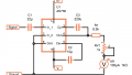
With the basic project components explained, let's starting building our voltmeter by wiring the Arduino-Potentiometer circuit. The Arduino-Potentiometer circuit is basic in design. It consists of a 10K-ohm potentiometer's wiper arm wired to the "A0" (analog pin 0) of the Arduino Uno. The other two remaining pins of the 10K-ohm potentiometer are wired to +5V and GND(ground) of the Arduino Uno. The circuit schematic diagram is shown next. This voltage divider circuit will provide a range of input voltages (0V to +5V) for our analog voltmeter to measure and display voltage values on the virtual instrument panel (GUI).

A 10k-Ohm potentiometer is wired to the Arduino Uno's pin "A0". The other two pins are wired to +5V and GND (ground).
As an additional reference for building an alternate input variable voltage circuit, I've included the littleBits slide dimmer control electrical wiring diagram:
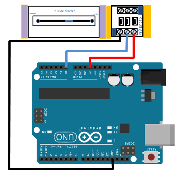
The electrical wiring diagram of the Arduino-littleBits slide dimmer control circuit.
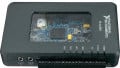
The littleBits slide dimmer control requires a +5VDC and ground power supply to properly operate it. The Arduino's +5VDC power can easily operate the littleBits electronic module. The proto-board is used to wire the slide dimmer control to the Arduino's onboard +5VDC power supply. The slide dimmer control analog signal is wired to "A0" Arduino pin. Additional information about the proto-boards terminal blocks' definitions is shown below. To provide additional support for the slide dimmer and the proto-board, place them on a littleBits mounting board.

The proto-board allows the ease of wiring external circuits to the littleBits electronic modules.
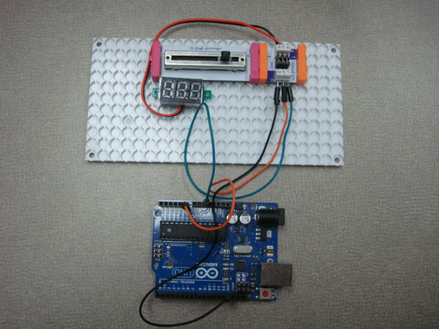
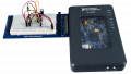
After wiring the electrical-electronic components to the Arduino, the final control circuit should look similar as shown in the next figure. The small voltmeter provides a quick method of monitoring the varying voltage signals created by the slide dimmer control.
The final steps to the project include
- Attaching the the Arduino to your desktop pc or notebook computer's USB port
- Opening the LabVIEW software
- Executing the analog.vi block diagram
- Configuring the analog voltmeter's control panel with the following settings:
a) Serial Port: COM x (x is the actual port your Arduino Uno is attached to)
b) Al Channel: 0
c) Reference: x ( x is the threshold voltage value for detection)
5. Click the arrow button on the LabVIEW menu.
The control panel will be displayed on your screen as shown next.

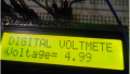
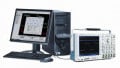
Attaching a digital voltmeter to the proto-board for measurement comparison shows an equivalent voltage reading.

To see the actual analog meter in action, check out the video clip.
While watching the digital voltmeters (the small and traditional measuring instruments), adjust the slide dimmer control to provide an input voltage of 1.5V to the Arduino Uno. Compare this reading on the digital voltmeter to your LabVIEW based analog voltmeter. Make a data table comparing the voltage readings of all three voltmeters. Create a plot showing the relationship of the voltage readings recorded onto the data table.
LINX-Analog_Read_1_Channel_Gauge_LED.vi.zip
Give this project a try for yourself! Get the BOM.


Did you have arduino code for this?