 Facebook
 Google
 GitHub
 Linkedin
What’s the LabVIEW FPGA? Learn It Now!
Learn LabVIEW FPGA by programming the on-board Xilinx FPGA of the student-focused embedded device NI myRIO.
Learn how to start programming the on-board Xilinx FPGA of NI's myRIO. It will start by explaining the basics of what FPGA is and move towards simple interfacing such as blinking an LED on the device. Finally, the series will move towards more advanced topics such as implementing a FIFO and importing 3rd party code (VHDL/Verilog).
Related Articles
Using LabVIEW FPGA on NI myRIO (links will be added as the series progresses):
Part 1: What is LabVIEW FPGA
Part 2: Hello World (Blinking an LED)
Part 3: Reading Analog Values
Part 4: FIFOs
Part 5: 3rd-party Code
Overview
This is Part 1 of Articles Series called "Using LabVIEW FPGA on NI myRIO". The series will cover an array of topics starting with introduction to what LabVIEW FPGA is, it's benefits and how it relates to the NI myRIO embedded hardware device. What motivated me to cover these topics is the fact that there is a lot of information out there for professionals and advanced developers of LabVIEW FPGA, but entry-level content is scarse. Therefore I wanted to write a simple introduction, covering core concepts of hardware I/O, FIFOs and third-party code integration to hopefully help kick-start people's interest in programming FPGAs in NI LabVIEW environment. This article will focus on explaining what LabVIEW FPGA is, introduce the NI myRIO device and explain how to communicate between them.
LabVIEW (FPGA)
Firstly, I believe a brief introduction to LabVIEW is necessary to lay a solid foundation for the future material that will follow. In short, LabVIEW is a graphical programming environment developed by National Instruments and over the past 20-odd years has become a well-recognised tool in research and industrial engineering (specially with control, measurement, and test applications). Unfortunately, like many other industrial tools, it is not open-sourced or free; however, there are exceptions. For instance, as a student you can most likely acquire a free copy from your university, as LabVIEW is heavily tied to academia.
LabVIEW is powerful because it can allow complex programming tasks to be accomplished in a fraction of the time if you were to use other programming languages (that's right - LabVIEW is a full-blown turing-complete programming language). What is more, LabVIEW programming is essentially the same for any target, be it your PC, an Arduino or a type of National Instruments hardware (like the myRIO embedded device which we will use in this article series). The same environment and programming principles apply even to Field Programmable Gate Arrays (FPGAs) - reconfigurable hardware that can accomplish unprecendent speed and reliabiliy. If you have not come across FPGAs before, imagine them like a blank canvas of computer logic blocks which can be connected in different ways to cater to different functionality you specify in programming (See Figure 1). This functionality can vary from simple mathematical algorithms all the way to emulating your whole computer's CPU. Moreover code written on an FPGA can be truly parallel and re-programmed at any time, therefore it comes as no suprise that this technology has become extremely popular within the industry and its usage will only continue to grow. You might ask what the catch is? Well this technology implies relatively longer compile times (as the array of logic gates have to be electornically routed and it takes a lot of computational power). Moreover, conventially you must program FPGAs using proprietary languages such as VHDL and Verilog. In our case, we will use LabVIEW - a programming language that is uniform across all targets. While this tutorial will try to cater to widest possible audience, some basic understanding of LabVIEW is expected. You can get up to speed by reading the LabVIEW introductory videos provided by National Instruments.
.png)
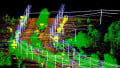
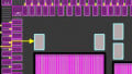
.png)
Figure 1 Simplified view of the FPGA - an array of logic blocks (Top) that can be connected in any way to build custom logic circuits (Bottom)
NI myRIO
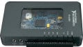
In 2013, National Instruments announced a student-focused affordable programmable hardware device called the NI myRIO (Figure 2). Imagine a cross of Raspberry PI and Beaglebone Black on steroids. Over the past few years it has proven to be an amazing piece of hardware that students and educators have used worldwide for many different projects and undertakings. The best part is that myRIO includes a Linux Real-Time Operating System (it is the Ångström distribution for those, who are curious) and an FPGA, therefore we can accomplish many different hardware interfacing and computational tasks with it. For the purposes of this tutorial I will focus only on the FPGA aspect of the NI myRIO, but it's important to understand that there is much more to it than what the series covers.

Figure 2 National Instruments myRIO embedded hardware device for students and hobbyists
Connecting to myRIO through LabVIEW
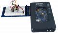
First and foremost we need to make sure our myRIO is powered from the DC power supply and connected to our development computer (Figure 3). Then, to establish a connection to the myRIO embedded target we need to create a LabVIEW project as shown in Figure 4 below. Here I am assuming that you already have LabVIEW, LabVIEW myRIO Toolkit and LabVIEW FPGA Modules installed on your machine. So let us open LabVIEW and on the splash screen select "Create Project." Select a Blank Project and save the new project as "myRIO FPGA Series 1.lvproj" anywhere on your machine. Next add myRIO as a new remote target (LabVIEW should automatically recognise the plugged-in device). The last step is shown in Figure 5.

Figure 3 myRIO connections

Figure 4 Creating a new LabVIEW Project

Figure 5 Adding myRIO as a new embedded target to our project
Compiling FPGA Code
Now that we have established a connection to the myRIO, we can start developing our very first and most basic LabVIEW FPGA application. Firstly we must create a new FPGA VI under the newly-created target. A refresher - Virtual Instrument or simply VI is essentially just a piece of LabVIEW code that you run on different targets such as your PC or an embedded device (in our case it's the latter). Then on the Front Panel we will create two Numeric Controls (our operands) and one Numeric Indicator (our result). Now we can start programming on the Block Diagram where our source code resides. Here we will simply add two integers together and connect the resulting output to the Numeric Indicator as shown below. All of this will be eclosed in a while loop so the code can run continuously. Notice that the stop condition has False wired to it. This is because the FPGA loop will never stop, unless we cut the power to the myRIO of course. This is a common practise in LabVIEW FPGA development.
Then we can hit the Run Arrow, save the VI as "FPGA.VI" and compile our code. Notice that we can either compile it locally on our machine or on a could-server. In either of those cases it might take from a few minutes to several hours depending on the complexity of the application. This is because FPGA compilation is a computing-intensive process, however once compiled it happens to outperform regular computing methods in a number of applications, so it's worth the wait! The cloud-compilation is a faster way of getting the FPGA code compiled; however, for that you will need to create a FPGA Cloud Compile Service account which has a free trial of 90 days.

Figure 6 Creating a new VI and programming a simple adder in FPGA
Running FPGA Code
Finally, we can try running our code and checking if it works. If you completed all the steps correctly, you should see an interface where you can add two numbers. While not massively impressive, you should remember this is all running on FPGA (and updating at roughly 40MHz as opposed to 1KHz if you were to run it on a regular operating system, such as Microsoft Windows). Soon enough we will replace the dull math with something more exciting - interaction with the real-world. But for now I would like to congratulate you - you have just written and compiled your first FPGA application!
In the next article we will cover how you can adapt the knowledge gained here to make a blinking Light-Emitting Diode (LED) on the FPGA.
Next Article in Series: Learn LabVIEW FPGA on NI myRIO - Hello World!


article worth reading. halted my 1 hour internet search
Clear and to the point. They may want to continue the series.