 Facebook
 Google
 GitHub
 Linkedin
More First Order Opamp Circuits - Differentiators
All of our previous circuits dealt with opamps using resistors in the feedback loop. What happens when we start swapping out resistors for other passive components?
Do more than twiddle gain and phase!
Differentiate Yourself
All of our previous circuits dealt with opamps using resistors in the feedback loop. What happens when we start swapping out resistors for other passive components? Let's take the inverting amplifier circuit that we looked at in the last opamp article and replace the input resistor Rin with a capacitor.
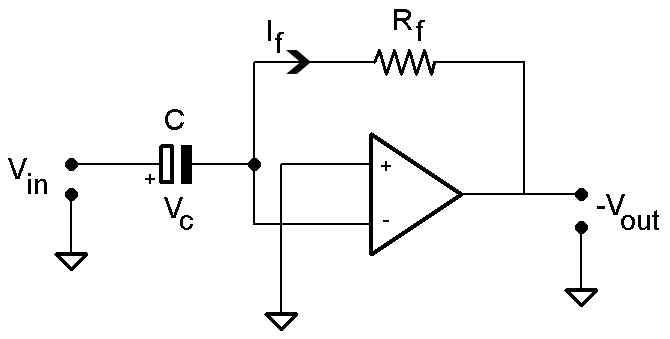
Figure 1: A Different Inverting Circuit
First thing's first - let's figure out the gain of this circuit. If we recall from our first article, we know that the current through the feedback path has to be equal to the current through the input path. The current through a capacitor is given by the following equation:
\[{i_{C}}=C\frac{dv}{dt}\]
When we substitute that into the feedback equation, we get the following relationship:
\[i_{C} = -i_{R_{f}} \Rightarrow C \frac{dV_{in}}{dt} = - \frac{V_{out}}{R_{f}} \Rightarrow -RC\frac{dV_{in}}{dt} = V_{out}\]
This circuit is known as a _differentiator_, because the output is proportional to the first derivative of the input voltage. We can see a few examples in the following image.
Figure 2: Differentiator Input/Output Waveforms
The sine wave shouldn't be surprising - the first derivative of a sine wave is a cosine wave. You can see that the differentiator output reflects this in the form of a phase shift, with the output lagging the input by 270 degrees (90 for the cosine shift, 180 for the opposite polarity). A triangular wave has a constant rate of change until it changes direction. The differentiator responds to this sort of wave by fixing the output at a DC level proportional to the slope of the triangular wave, multiplied by the passive values RC. The square wave ends up producing a series of quick pulses out of the differentiator. These pulses represent the very quick transitions of the square wave's edges. An ideal differentiator would output an impulse signal in response to an ideal square wave; this example has a slight trailoff that represents a square wave reaching its final value.
A Matter of Frequency
One thing we've put off discussing is the frequency response of a differentiator circuit. Since this differentiator employs a capacitor in its input path, we know that its performance will be subject to some effects of frequency just by virtue of the capacitor's presence. We can derive the differentiator's transfer function pretty handily by shifting it into the Laplace domain, where a first derivative equals multiplication by `s`:
\[RC\frac{dV_{in}}{dt} = V_{out} \Rightarrow RCs(V_{in}) + f(0) = V_{out}\]
\[\frac{V_{out}}{V_{in}} = RCs \Rightarrow \frac{V_{out}}{V_{in}} = RCj\omega\]
(Note - we'll assume the capacitor in this example is discharged so we can eliminate the f(0) term.)
Cool! Let's generate a Bode plot of this circuit to get an idea of how its response changes with frequency.
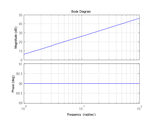
Figure 3: Differentiator Bode Plot
As you can see, phase of the output is always shifted 90 degrees from the input. You can also see that the magnitude of the gain is increasing without bound as frequency increases. As long as the frequency of the input is above the unity gain frequency, it's going to get amplified. (As an aside - can you see what the unity gain frequency is?) In a way, that's kind of cool - we've found a circuit that can supply gain proportional to frequency! In practice, though, it's not so cool. Since gain is increasing with frequency, it means that differentiators are exceptionally sensitive to noise, especially high frequency noise. Thus, it's sensible to limit the gain, for the sake of having a circuit that's not drowned in noise!
Reasonable Limits
Ideally, we'd like the signals in the band region of interest to have a moderately level gain applied by the differentiator. To achieve this, we need a way to compensate for the monotonic increase in gain at high frequencies. The simplest way to achieve this is with a few extra components:
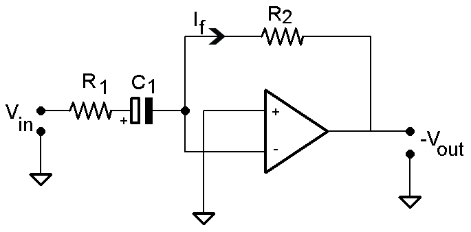
Figure 4: Differentiator with Added Input Resistor
The easiest addition to make is an extra resistor to the input of the differentiator. As frequency of the input signal increases, the impedance of the capacitor will trend towards zero. The effect of this is pretty convenient:
\[ i_{f} = \frac{V_{in}}{(R_{1} + \frac{1}{sC})} = \frac{- V_{out}}{R_{2}}\]
\[\left | \frac{V_{out}}{V_{in}} \right | = \frac{R_{2}}{(R_{1} + \frac{1}{sC})}\]
As \[s \Rightarrow \infty , \frac{1}{sC} \Rightarrow 0\]
\[\left | \frac{V_{out}}{V_{in}} \right | \approx \frac{R_{2}}{R_{1}}, for freq > \frac{1}{R_{1} C_{1}}\]
At high frequencies, this circuit stops behaving like a differentiator and starts behaving like a simple inverting amplifier. Sweet! We've managed to bound the gain of high frequency noise. What if we want to take it a step farther, and actively reduce the high frequency noise?
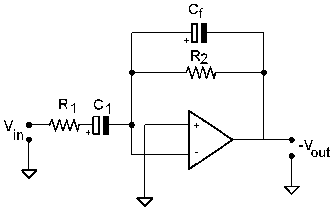
Figure 5: Differentiator with Added Input Resistor and Feedback Capacitor
An additional cap in parallel with R2 will end up having similar behavior as C1. At a certain frequency, it will start to behave as a low impedance that just gets lower as the frequency rises. The effect on the feedback path is to slowly short out the feedback resistor R2 at higher and higher frequencies. This is effectively the same as decreasing the resistance of the feedback resistor Rf in an inverting amplifier - the parallel cap allows you to keep the gain for higher frequencies down.
Why do we care about limiting high frequency noise in differentiators so much? The simple answer is stability. As you've probably noticed in our last article on opamps, all of the opamp circuits we've seen employ feedback.
Wrapping Up
Differentiators are amazingly useful in control circuits, where it's frequently useful to monitor the rate of change of a plant. With a little tuning, they're very simple to make work for you!
By the way - did you figure out the unity gain frequency of the ideal differentiator? Just so we don't leave you hanging:
\[\left | \frac{V_{out}}{V_{in}} \right | = 1 = \omega RC \Rightarrow \omega_{o} = \frac{1}{RC}\]
Until next time!
Related Content


Very nice article. Thank you!