 Facebook
 Google
 GitHub
 Linkedin
Navigating the Boost Converter’s Vulnerability with Alternative Power Conversion Topologies
Here are some great power conversion topologies that can be used as alternatives to the boost converter; they are much less vulnerable to short circuit load conditions.
A previous article points out the vulnerability that boost converters have to short circuit load conditions. The article explored how MOSFETs, load switches, switching controllers with built-in protection, and fuses can be used to protect a boost converter from catastrophic failure. This article discusses alternate power conversion topologies that are less vulnerable to short-circuit load conditions than the boost converter.
.jpg)
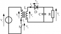
Figure 1: Boost Converter
Alternative Power Converters to Use Instead of the Boost
There are alternative power conversion topologies that can be used instead of the boost converter to produce an output voltage that is higher than the input voltage. Some of the most common are the flyback, SEPIC, and buck boost converters. These converters are not vulnerable to short circuit load conditions as the boost converters. These converters are step-up/step-down converters, meaning that they can produce an output voltage higher or lower than the input voltage. This step-up/step-down functionality adds flexibility to the design, although solutions using these topologies may be less efficient or more costly than a simple boost converter. Many DC-DC converter controller chips that drive these topologies feature current mode control, which features an additional level of short-circuit protection. These topologies don't inheriently protect against circuit circuit loads on their own, but they can shut down in a way that stops the flow of current if a short-circuit load is detected. Some dc-dc converter controller chips may include short-circuit proteciton, while others might require extra components to make this happen. All of these topologies are less vulnerable than the boost converter. It is up to the designer to decide if one of these topologies is a good replacement for the boost converter for a particular design.
Flyback Converter
The flyback converter is a step-up/step-down DC-DC converter. The ratio between input and output voltage is $$Vout/Vin = N*D/(1-D)$$. Figure 2 is a simplified schematic of the flyback converter. Notice that if a short circuit is detected, the MOSFET in the schematic may be turned off to protect the converter. Some flyback controller ICs feature current-mode control, which limits the inductor current. This provides additional short circuit protection.A boost converter can be changed into a flyback by replacing the inductor with a coupled inductor.
.jpg)
Figure 2: Simplified Schematic of a Flyback Converter
Figure 3 is a simplified schematic if a synchronous flyback converter. In a synchronous converter, the diode is replaced by a MOSFET to enhance efficiency.
.jpg)
Figure 3: Simplified Schematic of a Synchronous Flyback Converter
Some advantages of the flyback topology include:
- Short circuit protection.
- Needs only one MOSFET and one diode.
- Better wide range regulation than a boost converter
- Can be isolated.
- Can be a cheap solution
Some disadvantages of the flyback topology include:
- Needs a coupled inductor.
- MOSFET sees higher voltage spikes because of transformer
- May need a snubber circuit to dissipate the voltage spikes.
Examples of a synchronous flyback controller is Microchip's MCP19115. The MCP19915 is a flyback and boost controller that integrates a microcontroller. It can do synchronous or non-synchronous converters.
An example of a non-synchronous flyback controller is Linear Technology's LT3748.
SEPIC Converter
The SEPIC converter is a flyback with a DC blocking capacitor placed between the windings. The ratio between input and output voltage is $Vout/Vin = D/(1-D). Figure 4 is a simplified schematic of the flyback converter. This schematic shows a SEPIC built using a coupled inductor, to reduce board space. ce that if a short circuit is detected, the MOSFET in the schematic may be turned off to protect the converter. The DC blocking capacitor also adds short circuit protection. Some SEPIC controller ICs feature current-mode control, which limits the inductor current. This provides additional short circuit protection. A boost converter can be changed into a SEPIC converter by adding a DC blocking capacitor, and using a coupled inductor or 2 separate inductors.
.jpg)
Figure 4: Simplified Schematic of a SEPIC converter
Some advantages of the SEPIC tology are:
- Step-up/step down converter.
- Needs only one MOSFET and one diode.
- Short circuit Protection.
Disadvantages:
- Needs a second inductor or a coupled inductor.
- More complicated circuit to stabilize.
- DC Blocking Cap needs to be rated to carry all load current.
A good example of a switching controller than be used to build a SEPIC converter is Microchip's MCP1630, although any boost controller chip can drive a SEPIC controller.
Buck-Boost Converter
The buck boost converter is really a buck converter combined with a boost converter, using a single inductor. The ratio between output voltage and input voltage is $Vout/Vin = D/(1-D). The MOSFETs can be turned off if a short circuit load is detected. Many buck-boost converters feature current mode control, which limits the inductor current, providing additional short circuit protection. This circuit uses four switches. It uses two MOSFETs and two diodes, or comes in a high efficiency version that uses four MOSFETs. This converter costs more than other converters because it requires specialized converter controllers that are less common than buck, boost, flyback, or SEPIC converters. The four switches also add cost.
.jpg)
Figure 5: Non-synchronous
.jpg)
Figure 6: Synchronous buck boost
Some advantages of the buck-boost topology include:
- Short Circuit Protection
- Step-up/step down,
- No coupled inductor.
- Some converters switch between buck and boost mode to improve efficiency.
- Work over a wide range of inputs.
- Can be implemented as a synchronous converter to improve efficiency.
Some disadvantages of the buck-boost topology include:
- Requires 4 switches.
- Controller ICs are less common than flyback, boost, SEPIC controllers and cost more.
- Each switch is a lossy element, which reduces efficiency.
A good example of a non-sychronous buck-boost controller is Texas Instrument's LM5118. It features current mode control, which limits the cycle-by-cycle inductor current. This adds an extra level of short circuit protection. A good example of a synchronous buck-boost controller is Linear Technology's LT8490 controller.
Conclusion
This article has discussed how flyback, SEPIC, and buck-boost converter topologies may be suitable replacements for a boost converter when a designer is worried about short-circuit load conditions. Besides being less vulnerable to short circuit loads, these power conversion topologies also have the flexibility of being step-up/step-down converters. The flyback and SEPIC converters can be built by making simple modifications to a boost converter, while a buck-boost converter requires two additional switches and a special switching regulator.
Related Content


What is the difference between schematic 2 and schematic 3?