 Facebook
 Google
 GitHub
 Linkedin
One Circuit, Three Bode Plots: The Omnifilter
This article, part of AAC’s Analog Circuit Collection, discusses a filter circuit that allows you to choose between a low-pass, a high-pass, and a band-pass response.
This article, part of AAC’s Analog Circuit Collection, discusses a filter circuit that allows you to choose between a low-pass, a high-pass, and a band-pass response.
There are times when convenience and flexibility are more important than cost and PCB real estate. Such situations are becoming increasingly rare, but surely there is still room in this world for a larger, somewhat more expensive circuit that can be used—without a single modification—as a low-pass filter, a high-pass filter, or a band-pass filter.
“What is an omnifilter?” you ask, followed by, “and why have I never seen this word before?” The second question is easy to answer: because I made it up. Regarding the first question, an omnifilter is an inaccurately named circuit that gives you three frequency responses for the price (or maybe a little more than the price) of one. The name is inaccurate because the prefix omni comes from the Latin omnis, meaning “all,” whereas there are two filter types that are not included in the omnifilter, namely, notch and all-pass.
Low-Pass, High-Pass, Band-Pass
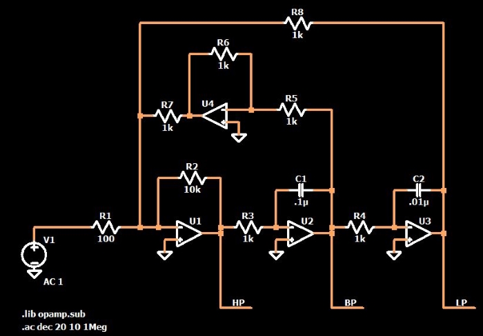
Without further ado, let’s take a look at the circuit, which is similar to something that I found in Principles and Applications of Electrical Engineering (fourth edition):
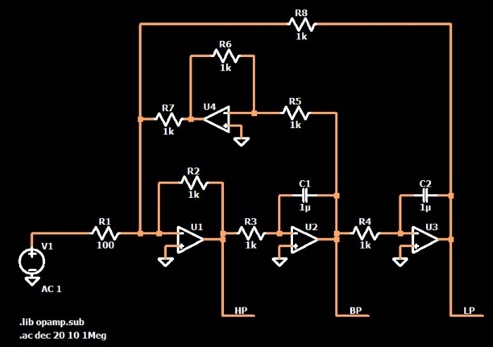
So the general idea here is a circuit that has one input signal and three output signals. The output signal from the first op-amp is a high-pass-filtered version of the input signal, the second op-amp produces a band-pass-filtered signal, and the third produces a low-pass-filtered signal.
I’ll tell you right now that this circuit defies my attempts to analyze the general functionality. There are a total of five feedback paths, one of which applies a 180° phase shift. The high-pass response comes from a subcircuit that looks like an ordinary inverting amplifier, and the low-pass response comes from a subcircuit whose input is a band-pass-filtered signal. Somehow, though, it does work (at least in the simulation world).
And just for the record, this circuit is not quite as impractical as it might first appear. Let’s say you include an omnifilter on a PCB because you’re not yet sure what sort of frequency response you will need, or (and this is probably a more likely scenario) because you want the board to be “multi-purpose,” i.e., something that can be incorporated into a variety of different systems. It might seem highly inefficient to use four op-amps instead of one, but four is actually a good number, because op-amps are readily available in quad packages, and these quad parts can be quite small and very reasonably priced. One example that I came across is the LM324QT from STMicro; it has four general-purpose op-amps in a 3 mm × 3 mm package, and it costs less than 50 cents.
Gain and Frequency Response
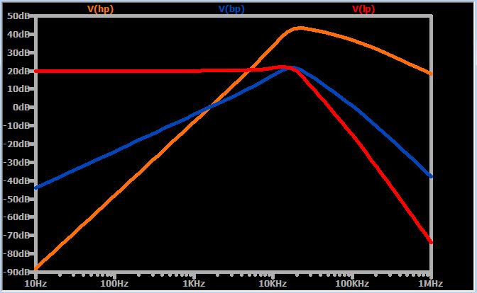
The following plot shows the three filter responses for the schematic given above.
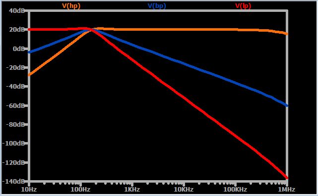
As you can see, the low-pass cutoff frequency is close to the high-pass cutoff frequency, and both of these are close to the band-pass center frequency. Something else that I find surprising, almost amazing, is that the low-pass and high-pass responses are actually second-order: the roll-off is 40 dB per decade. Maybe this is just ignorance on my part, but by looking at this circuit I would never expect it to produce two second-order filter responses in addition to a band-pass response. It seems to me that we’re getting quite a lot of functionality from four op-amps and a moderate quantity of resistors and capacitors.
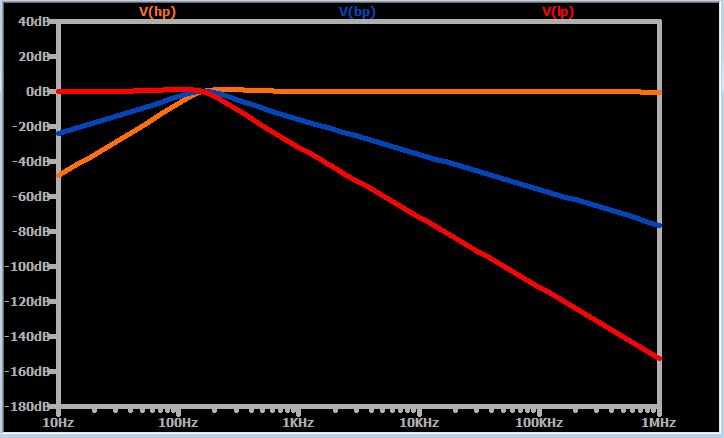
Another handy feature of the omnifilter is the ability to change the gain of all three filters by modifying just one resistor, namely, R1. The gain will be R2/R1. In the previous plot, R2/R1 = 1 kΩ / 100 Ω, and consequently all of the filters have a maximum magnitude response of 20 dB. If I change R1 to 1 kΩ, the responses look the same but they are shifted down to unity-gain:
Regarding the cutoff frequency, you probably noticed that the LTspice implementation is full of 1 kΩ resistors and 1 µF capacitors. If we apply the typical fc = 1/(2πRC) formula, we would expect a cutoff frequency of ~160 Hz. Unfortunately, setting the cutoff frequency is not quite as straightforward as setting the gain: as the next plot shows, the –3dB frequency is ~203 Hz for the low-pass filter and ~125 Hz for the high-pass filter.
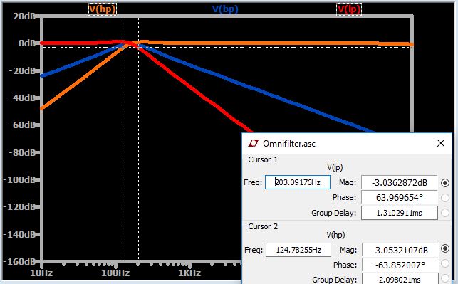
(It’s interesting to note that the two –3dB frequencies are almost equidistant from the expected 160 Hz cutoff, and that the band-pass center frequency is 160 Hz). I don’t know how to calculate the component values based on the desired cutoff frequency. My recommendation is to simulate until you find something that works.
One Cutoff Frequency, or Three?
I envision the omnifilter in applications that do not require filters with significantly different cutoff frequencies. And furthermore, I suspect that the topology does not allow for this; restricting the filters to one common cutoff frequency is surely part of the trade-off that allows this four-op-amp circuit to produce two second-order responses in addition to a band-pass response.
As a quick example before we finish up, the following circuit has been modified in a way that one might expect to lead to different cutoff frequencies (R2, C1, and C2 have been changed). But as the plot demonstrates, such is not the case.
Conclusion
We’ve looked at a complicated, honestly rather baffling, circuit that provides some interesting functionality. The omnifilter is an extensible filtering module that is not easy to analyze, but with the help of SPICE simulations it could perhaps be a valuable circuit in certain applications.
Feel free to download my LTspice schematic by clicking on the orange button, and if your simulations reveal any interesting characteristics of this circuit, by all means, share them in the comments section below.
Related Content


Why has the author of this article gone out of his way to rename the STATE VARIABLE FILTER to something else, and then try and justify it with specious gobbledygook about the origins of “omni”?
He then goes on to say that this “omnifilter” can’t “do” a NOTCH, when in fact, if one sums the HP and LP outputs you get a notch filter.
As for the “all pass” filter, it’s used in rather specialized instances (adjusting phase for instance) and not hard to implement. Google it.
You end with “complicated, honestly rather baffling, circuit” when, through the math is “tough”, it is possible (I do it in an Excel spreadsheet).
If you want to help your readers, don’t make stuff up, direct them to real resources that are actually helpful. Here’s a link to get you started: https://www.electronics-tutorials.ws/filter/state-variable-filter.html
I see this article as an excellent thread starter. I would be interested in hearing from others that can comment constructively upon some of the questions/issues raised by the author.