Facebook
 Google
 GitHub
 Linkedin
Exploring Power Transformer Protection for Power Systems: Failure Types and Differential Protection
Learn why power transformers are important, where they can fail, and why protection systems are crucial.
Learn why power transformers are important, where they can fail, and why protection systems are crucial.
The power transformer is the most important and the most expensive part of the electrical system. Its main task is to transform electrical energy from one voltage level to another. The function of all other electrical equipment (circuit breakers, instrument transformers, etc.) is to protect the power transformer.
Considering the importance of the transformer and its high cost compared to other equipment, it is reasonable to install high-quality systems for protection against external failures from the network or internal transformer failures.
Transformer Protection Systems
External failures which appear somewhere in a network (overvoltage, short circuit, overload, atmospheric discharge, etc.) can cause troubles for transformers (a part of that network). For example, short circuits in the network can cause significant heating of the transformer busbars and windings. Copper losses (RxI2) are increased with the square of the current and dissipated as heat.
Failures can appear inside the transformer, as well, such as windings short circuits, inter-turns short circuits, short circuits between phases, or faults in the core, transformer tanks, or breakthroughs on the transformer bushing. When it comes to failure location, the transformer protection systems can be divided into external and internal protections.
The main job of the protection system is to separate the transformer from the energy supply as soon as possible, preventing unintended consequences and major transformer damages. The protection system is designed to be able to signal if irregularities have occurred in the electrical system, which could lead to transformer failure.
After a pre-set relay blocking time (operation time delay), the protection system sends a signal to the circuit breaker, which removes the transformer from the system before the failure affects it.
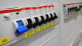
A transformer substation with a protected transformer, circuit breaker and measurement current transformers is illustrated in Figure 1 below.

Figure 1. A transformer substation with a protected transformer, current transformer, and circuit breaker
Transformer Protection Systems Based on Operation Criteria
You can see different transformer protection systems according to operation criteria listed in Table 1 below.
Table 1.
| Operation Criteria | Protection System | Failure Location (Internal/External) |
|---|---|---|
| Current differences criteria | Differential protection | Internal/external protection |
| High current criteria | Overcurrent protection | External protection |
| Gas evaluation criteria | Buchholz relay | Internal protection |
| High-temperature criteria | Thermal overload protection | Internal protection |
| Zero-sequence current criteria | Ground fault protection | External protection |
| Line impedance criteria | Distance protection | External protection |
Transformer Protection Types by Failure Conditions
Different protection systems can detect different faulty conditions in the transformer.
Table 2 shows which failures can be detected with which corresponding protection system.
Table 2
| Transformer Faulty Conditions | Protection System |
|---|---|
| Transformer overloading or overheating | Thermal overload protection |
| The external short circuit in the network | Overcurrent and distance protection |
| The transformer internal short circuit | Differential, overcurrent and Buchholz relay |
| The transformer internal single phase short circuit or ground-fault | Single phase overcurrent, ground fault and tank ground-fault protection |
What Is Differential Protection (ΔI)?
Differential protection (ΔI) is a reliable and safe protection method, as well as the most important and most commonly used transformer protection. It is used for protecting the transformer with nominal power above 8 MVA. It is usually not used in the case of a transformer with lower nominal power up to 4 MVA.
Differential protection covers almost all short circuits inside the transformer such as short circuits between phases, inter-turns, and between phase and ground. If the transformer neutral is directly grounded, this protection also covers insulation breakthrough through all windings. If the transformer neutral is isolated, the differential protection covers only faults between two phases but not single phase failures.
The differential protection operation principle is based on comparing the output and input transformer currents as illustrated in Figure 2.

Figure 2. A diagram of a differential protection scheme
In normal network conditions, a transformer operates with the nominal current. The current transformers (CT in the diagram above) are selected with corresponding turns ratio such that the currents in the CT's secondary sides are equal.
In this case, there is no current flow through the differential protection (ΔI=0) because the CTs' secondary currents have equal amplitude and phase displacement value. The differential protection will not operate at this point. In faulty conditions, the transformer current value will be much higher than the nominal current, which will cause ΔI>0. In this case, the protection will operate and take the transformer off of the service.
Challenges of Utilizing a Differential Protection System
Theoretically, this protection system seems very simple. But, in reality, the protection operating criteria is not so simple at all.
The challenges facing differential protection are listed below:
- The primary and secondary transformer currents are usually different. The current transformer should be properly selected so that the differential current in normal conditions is ΔI=0.
- Different transformer vector groups have different current phase displacement on the primary and secondary side.
- The CTs on both transformer sides should have approximately the same saturation characteristics regarding the knee point and saturation curve.
- The tap changer operation (transformer voltage regulation) can cause the ΔI current to go through the protection circuit because of the changing transformer turns ratio.
- When the transformer is first energized, it causes the current in only one transformer side, disturbing the differential protection balance.
- CT saturation and the DC current component phenomenon cause current differences.
- The external ground fault in an electrical system from the low voltage transformer side can cause the zero-sequent current component, which can operate the ΔI.
Analog and Digital Differential Protection
Nowadays, analog and digital differential protection can both be found in electrical systems. The analog system uses old-fashioned mechanical solutions while new digital technology solves these issues by using software.
New electrical systems are designed according to digital protection systems. Digital systems use interconnection transformers, higher-threshold ΔI values, chokes (inductors), and capacitors. A software process addresses all the mentioned requirements on the differential protection. The purpose of the interconnection transformers is to filter the zero-sequence current component, which appears due to external ground fault in a network. Those transformers should be connected in the Yd vector group.
How to Choose a Threshold Differential Protection Current
It is very tricky to set the corresponding threshold differential protection current. It should be low enough to detect a faulty current and take a transformer off the service in a short period of time. But, on the other hand, it should be high enough to avoid the wrong operation in some regular transformer condition such as first energization (higher current), no-load current (DC current component), etc.
If the remnant flux is present in the transformer core when it is first energized, the inrush current value can reach almost the short circuit current value. Because of this, it is necessary to predict protection operation delay when the transformer is first energized. The startup transformer current contains conspicuous second harmonic and DC current components. The slowly reducing DC component and its high value can saturate the CTs and cause incorrect current measurement. Because of the above the operation threshold, ΔI is usually set as 20-40% of the nominal current value (20% transformers without tap changer and 30-40% with tap changer).
ΔI should be low enough to cover internal short circuit failures. The differential protection should operate as quickly as possible (in practice, ~25-40 ms) to decrease fault energy, which destroys the transformer. When the differential protection solution has detected the protection, it sends the signal for circuit breaker operation and an alarm is triggered.
In practice, before putting the transformer in service again, the transformer must be tested in detail and the failure causes analyzed.

Figure 3. A Siemens digital protection system. Image used courtesy of Zen 38 [CC BY-SA 3.0]
New digital ΔI solutions perform the DC current component filtering by using software. The software gives the signal to the protection system, which will block the DC current component protection operation by using an electronic circuit.
The software usually uses algorithms for current wave analysis. The main requirements for those algorithms are even harmonics detection (important for detecting magnetization current), the DC current component, and fifth harmonic detection. All of these are important to divide the transient disturbances and faulty conditions.
According to the calculated harmonics amplitude, the blocking signals are defined (relay logic). The protection system manufacturer gives a range of blocking thresholds, but the customer (that is, electrical engineer) should set the corresponding threshold according to the experience and characteristics of the protected transformer.
Here's a closing remark for electrical engineering students and young engineers: The installation, adjustment, programming, and testing of protection systems is a very popular profession nowadays. Usually, digital protection systems are installed in all new substations. Each protection system should be routinely tested and maintained each year or every two/four years (depending on a customer’s policy). This is a modern and well-paid power engineering job.
Are you an expert in transformer protection? What's your experience with power systems? Share your thoughts in the comments below.