 Facebook
 Google
 GitHub
 Linkedin
Resistive Current Sensing: Low-Side vs. High-Side Sensing
What's the difference between high-side and low-side resistive current sensing? This article explains the basics, as well as when each is the more appropriate design choice.
Many applications, such as power management, battery charging, motor control, and overcurrent protection, can benefit from resistive current sensing. There are two options for placing a current sense resistor in series with a load: low-side and high-side current sensing.
In this article, we’ll look at these two arrangements and discuss their basic advantages and disadvantages.
Resistive Current Sensing
Resistive current sensing is widely used on printed circuit board assemblies when dealing with low to moderate current levels. With this technique, a known resistor Rshunt is placed in series with the load and the voltage developed across the resistor is measured to determine the load current. This is illustrated in Figure 1.
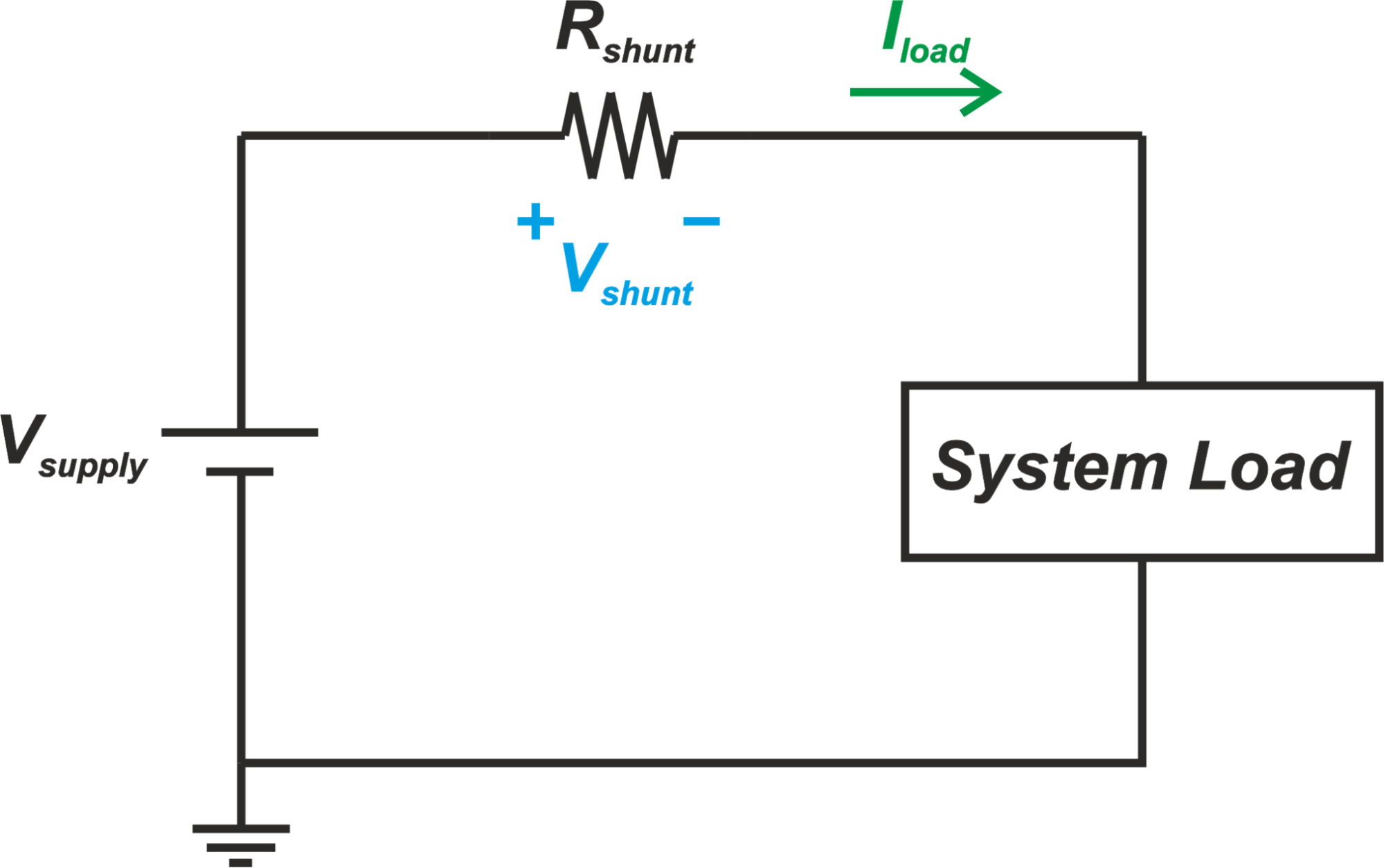
Figure 1
Current sense resistors, also called shunt resistors or simply shunts, usually have values in the range of milliohms. For very high current applications, the value of the shunt resistor might be even fractions of a milliohm to reduce the power dissipated by the resistor.
Note that even with small resistor values, the shunt power dissipation can be an issue, especially for high current applications. For example, with R=1 mΩ and I= 100 A, the power dissipated by the shunt resistor is:
\[P = R \times I^2 = 0.001 \times 100^2 = 10 W\]
A small resistor value also leads to a small voltage drop across the resistor. That’s why an amplifier is needed to convert the small voltage developed across the shunt resistor to a sufficiently large voltage suitable for upstream circuits.
We’ll discuss that, in high-side current sensing, the amplifier can have stringent requirements in terms of the common-mode rejection ratio (CMRR) specification.
Low-Side and High-Side Sensing
There are two options for placing a shunt resistor in series with a load. These two arrangements are referred to as low-side and high-side current sensing methods and are depicted in Figure 2.
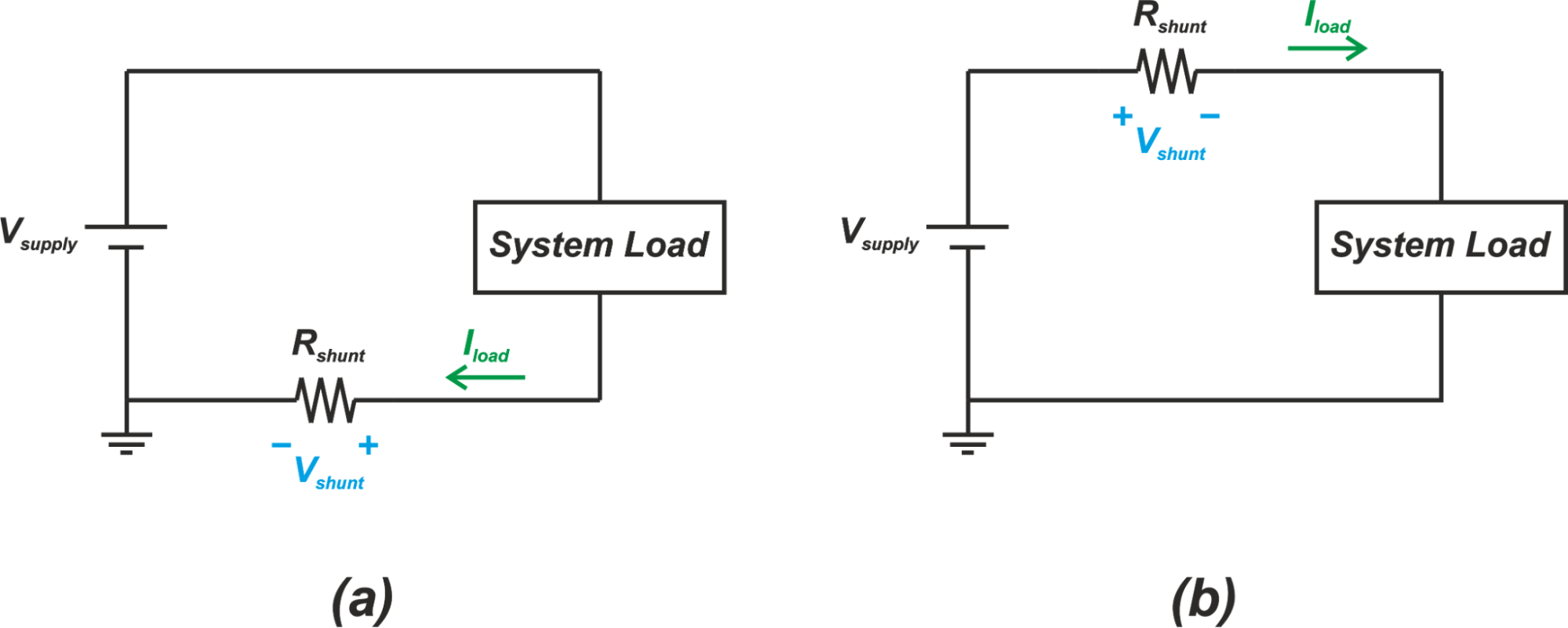
Figure 2. (a) Low-side current sensing and (b) high-side current sensing techniques.
In the low-side configuration, the current sense resistor (Rshunt) is placed between the ground terminal of the power supply and the ground terminal of the load. With the high-side method, the shunt resistor is placed between the positive terminal of the power supply and the supply input of the load.
Let’s see what are the advantages and disadvantages of each method.
High-Side Versus Low-Side Sensing: The Common-Mode Value
Assume that Rshunt=1 mΩ and I= 100 A. Even with this large current, the voltage drop across the shunt resistor is only 100 mV. Therefore, the common-mode value of the voltage across a low-side shunt resistor is only slightly above ground potential. And, for the high-side configuration, the common-mode level of the voltage across the shunt resistor is very close to the load supply voltage.
Since the amplifier used in low-side current sensing deals with a small common-mode voltage, it doesn’t need to have a high common-mode rejection ratio (CMRR). Common mode rejection ratio specifies how much attenuation an amplifier exhibits for a signal that is common to both inputs of the amplifier. Since the common-mode value is almost zero for a low-side current sensing configuration, the amplifier CMRR requirement is significantly relaxed and consequently, simple amplifier configurations can be used.
Figure 3 shows a basic amplifier that can be used in low-side current sensing.
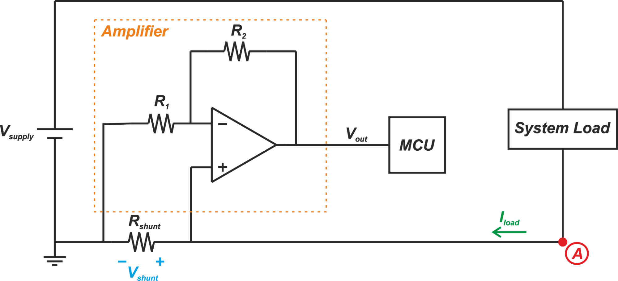
Figure 3
In this example, the amplifier consists of an op-amp and two gain setting resistors R1 and R2. Note that this is actually the non-inverting configuration of an op-amp. The more familiar schematic of this amplifier is shown below:
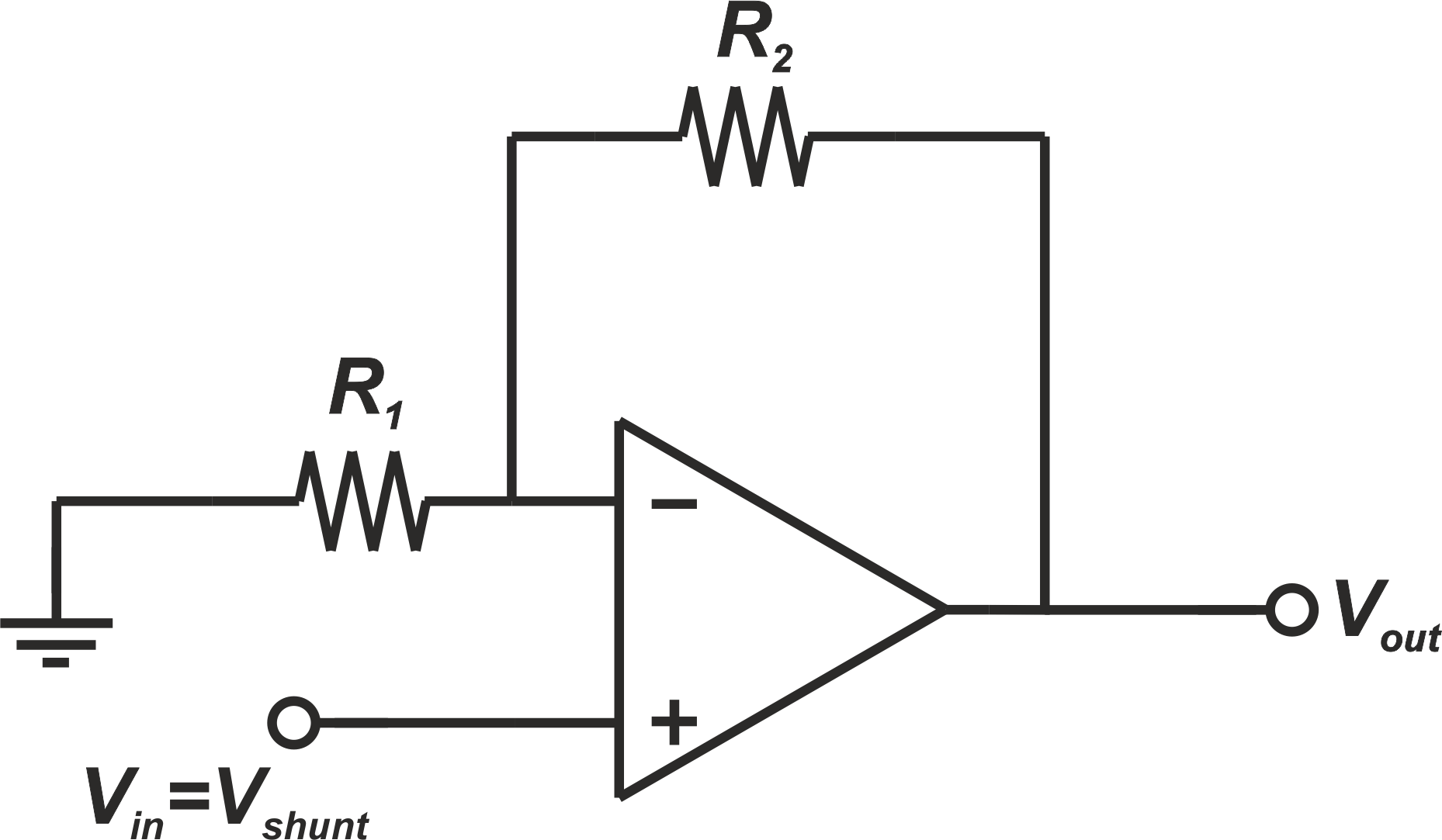
Figure 4
The output which is an amplified version of Vshunt can be found by the following equation:
\[V_{out} = \left(1 + \frac{R_2}{R_1}\right) V_{in} = \left(1 + \frac{R_2}{R_1}\right) V_{shunt}\]
On the other hand, an amplifier used in high-side current sensing needs to deal with a large common-mode voltage. The amplifier should have a high CMRR to prevent the large common-mode input from appearing at the output. That’s why specialized amplifier configurations are needed for high-side current sensing. These amplifiers should exhibit a high CMRR and support an input common-mode range up to the load supply voltage.
It is worthwhile to mention that there are many high-side current sensing applications, such as 3-phase motor control applications, where the load supply voltage is much larger than the supply voltage used for the amplifier. Hence, in a high-side sensing configuration, the input common-mode of the amplifier usually needs to be much larger than its supply voltage—a requirement that makes the amplifier design very challenging.
Low-Side Method Can Cause Ground Loop Issues
Although the low-side sensing method simplifies the amplifier design, it has a few disadvantages. Low-side current measurement places an additional resistor in the ground path. Hence, the ground of the monitored circuit is at a potential slightly higher than the system ground. This can become a problem for some analog circuits.
Since the ground of the monitored circuit is not at the same potential as the other loads in the system, there might be ground loop issues leading to an audible noise, such as a hum, or even interference with nearby equipment. Due to this limitation, low-side current sensing is usually used in applications where we deal with one isolated load or the load is not sensitive to ground noise. Cost-sensitive motor control in applications such as drones, drills, and reciprocating saws typically employ low-side sensing to be able to compete in the consumer market space.
Low-Side Method Cannot Detect Fault Detection
There are various fault conditions that low-side current sensing cannot detect. Figure 5 shows an example where a short occurs between the power supply of the monitored circuit and the system ground.
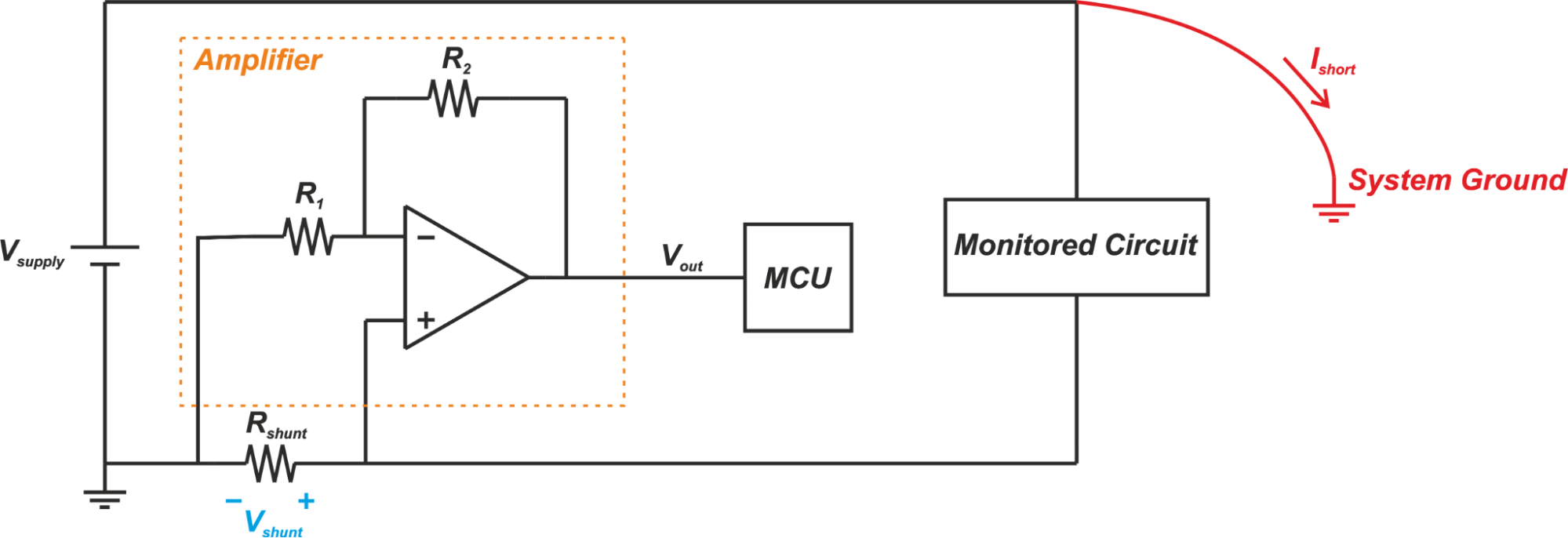
Figure 5
The fault current, Ishort, flows from the bus voltage directly to the system ground and does not go through the shunt resistor. Hence, the current monitor circuitry will not detect this fault condition. Low-side current sensing also cannot detect a short between the ground of the monitored circuit and the system ground (Figure 6).
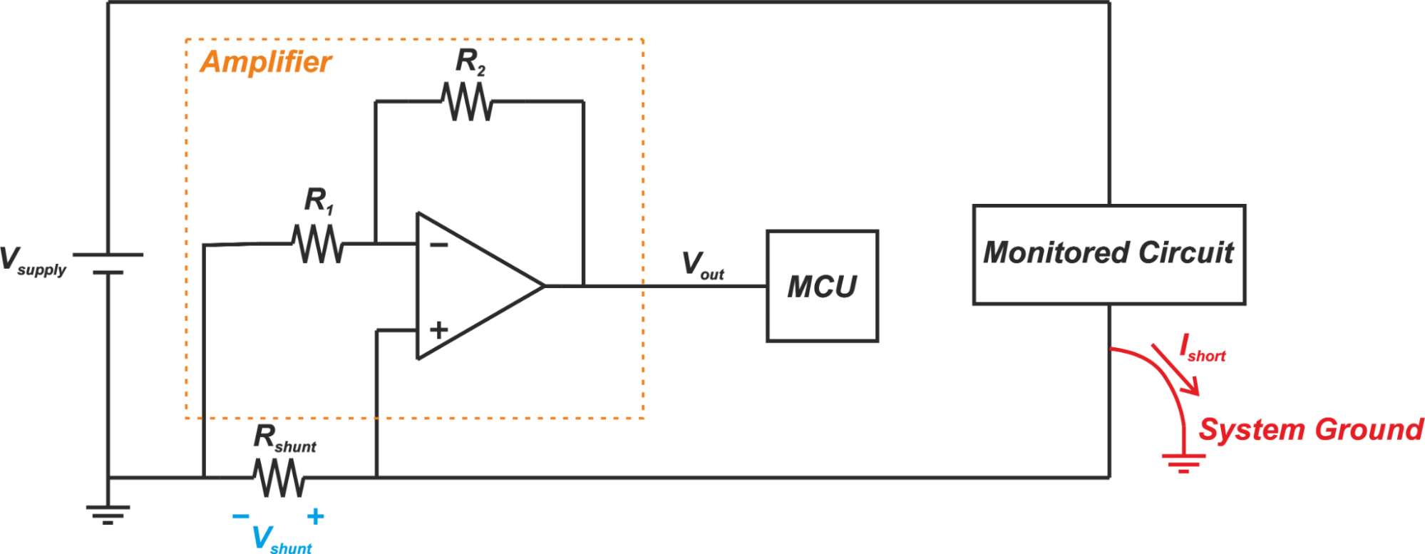
Figure 6
However, the high-side current sensing can detect the fault conditions that occur downstream from the shunt resistor. This is shown in Figure 7.
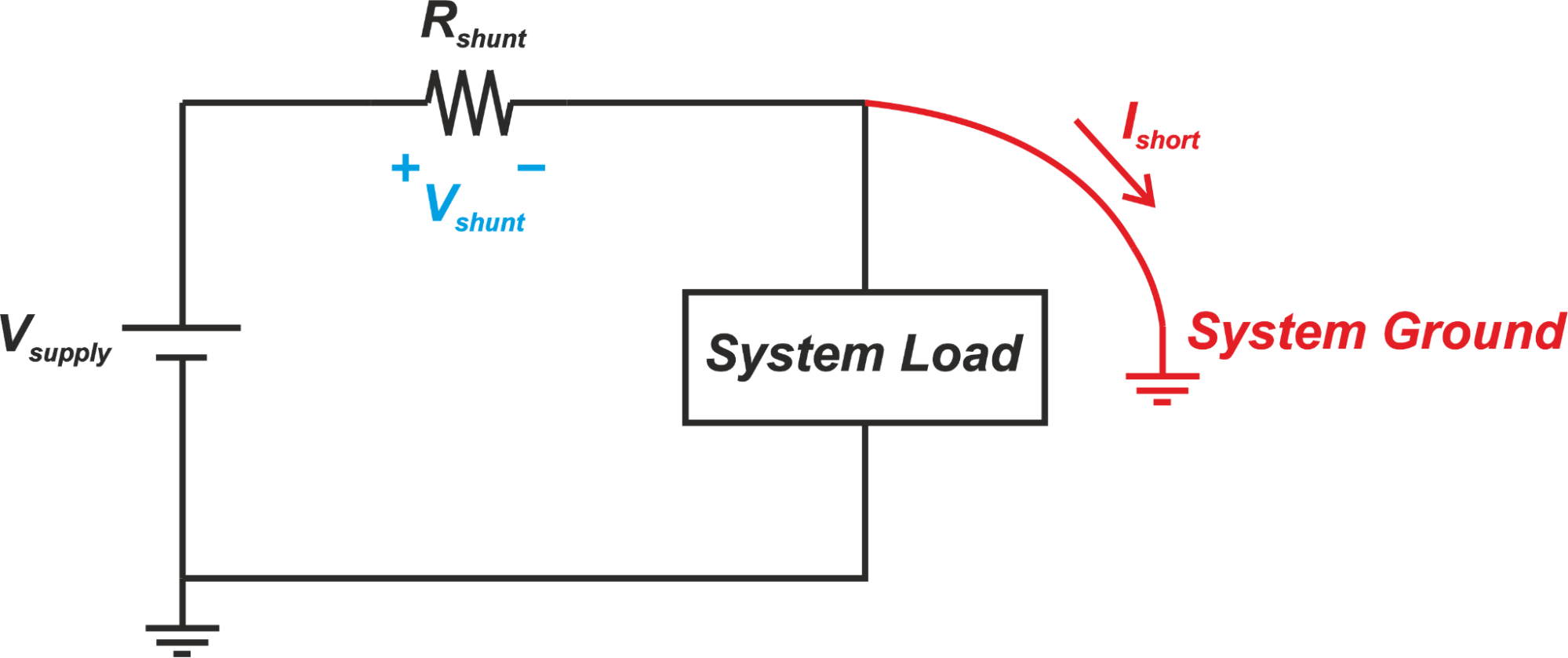
Figure 7
In this case, the fault current goes through the shunt resistor. Hence, the current measurement circuitry can detect the short condition and trigger the appropriate corrective action.
High-Side Current Sensing Can Simplify Wiring
Another drawback to low-side current sensing is that two wires are needed to power the monitored circuit even if the system ground is available. For example, in automotive applications, the car chassis serves as a common ground. With the chassis being at the system ground level, we only need a single wire for powering a load. However, if the current through the load is monitored by the low-side measurement technique, the system ground cannot be used and two wires are required for the load. Since the high-side sensing technique uses the system ground for the monitored load, it doesn’t suffer from this limitation. That’s why high-side sensing is better suited for automotive applications.
In the next article, we’ll examine the schematic in Figure 3 in greater detail. We’ll see that this structure is also susceptible to PCB trace resistance and a more accurate measurement can be made by means of a difference amplifier.
Conclusion
The main advantage of low-side sensing is that relatively simple configurations can be used to amplify the voltage across the shunt resistor. However, low-side current sensing is susceptible to ground disturbance and cannot detect fault conditions. Low-side current sensing is usually used in cost-sensitive motor control applications that need to be able to compete in the consumer market space.
To see a complete list of my articles, please visit this page.


Surely Rshunt is a complete misnomer?
Shunts usually bypass another component.
Up to now I thought sense resistors were Rsense.