Facebook
 Google
 GitHub
 Linkedin
Understanding Electricity with Hydraulics
An overview of how the concepts of electron flow and the role of individual circuit components can be related to the flow of fluid in pipe networks. The analogy between hydraulics and electricity is a useful tool for teaching and for those who are struggling to understand how circuits work.
Want to better understand the ins and outs of electricity? Read on!
A General Overview
It's not uncommon for someone (even those who take degrees with significant coverage of electricity and magnetism, such as physics and electrical engineering) to struggle with understanding how both a circuit as a whole and its individual components function. A common technique to solidify understanding is to learn the hydraulics analogy of electricity, which is arguably easier to visualize than electricity itself. First we'll cover component comparisons to real systems, followed by a bit about general analogies between electricity and water flow themselves, and finally a few places where the analogy breaks down. For the most part, the analogy only applies to DC circuits.
So how close does this analogy actually get? Well, it would be naive to say that there aren't some pitfalls to taking the comparison at face value. For example, while voltage is analogous to pressure in a hydraulic system (and current is analogous to water flow), there is a lower limit to pressure range, and a water reservoir (which is analogous to electrical ground) is required to avoid the creation of bubbles and voids (cavitation) in operation. Here are some other examples of breakdowns between the two:
- AC breaks down to a degree as part of this analogy. While at low frequencies it can be adequately represented by water reversing direction in a pipe system, higher rates of flow reversal comparable to that of high-frequency electrical signals cannot be achieved.
- Flow rates in hydraulics will be much faster than in an electrical system. While this might seem counterintuitive at first, remember that charge carriers in general move rather slowly in metal conductors, which feature resistance everywhere (a water pipe provides drag by its inner walls), and the resulting current of said charge carriers moving at the rate water does in common hydraulic systems would be huge. You can use Ohm's law to get an idea for current flow rate in a conductor, but compare with the equations here to see how "electrical" resistance (drag) operates on fluid flow.
- Some conventions regarding components themselves will be backwards. An example is a valve that is opened or closed and dictates whether or not fluid can flow in that section. While an "open" valve in the hydraulics allows flow, in an electrical circuit an open implies a break in continuity.
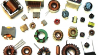
Basic Components - Wires, Resistors, Capacitors, Inductors
Note: The presence of a hydraulic pump is assumed with each of the following descriptions (it corresponds to the ideal voltage or current source in a DC circuit).
Wires and their relations to pumps are pretty straightforward, as the (live) copper wire or cable is directly analogous to a water-filled pipe. The resistance of the wire itself is analogous to the drag on the water flowing through a pipe. In this sense, a node (when analyzing a circuit using Kirchoff's Law) would be a T-shaped section of pipe.
The resistors are comparable to a section of the pipe network where the radius of the pipe is constricted, restricting the rate of fluid flow in that region, the same way that a resistor limits current. The resistor could also be compared to a filter of some sort, as long as it inhibits the passage of the water in the pipe.
Capacitors are like membranes blocking fluid flow in a pipe section. As the pump in the system begins pushing water, the membrane will stretch in response to the pressure from said water. The significance of the stretching is comparable to the amount of charged deposited on a capacitor. It should be fairly easy to see from this description that this membrane's stretching represents the voltage drop in an electrical circuit, and the discharge of a capacitor is likewise comparable to the membrane returning to its original extent.
An inductor is also very easy to compare, and if you've ever seen a water mill operating it'll be even easier. The inductor is like the wheel being propelled by the moving water; it will resist an initial flow or any change in flow once it is already turning at a steady rate.

Diodes, Transistors, and Other Bits
A diode in the hydraulic analogy compares pretty well to a ball check valve; if you do a quick Google image search you'll see all sorts of diagrams and product images, but below is one such example:

The ball check valve works by mounting the ball on a spring system, which is compressed by pressure buildup at the inlet port. This compresses the spring, allowing the flow of water forward, however if water were to flow in the other direction the gap would close again. This compares pretty well to the idea that a diode needs a certain forward potential in order to operate.
The transistor is, in my opinion, the coolest part of the whole analogy, because at first thought you might assume that it would be a much more complex component or flow section. This isn't the case at all! It can be represented effectively by a valve that moves in a perpendicular manner into and out of a flow path, increasing or reducing the amount of water that can be passed (although this would likely need to be controlled by its own pump system, or manually, to fully capture the way a BJT or FET transistor handles input and output).
![]()
As a final example we'll look at the op-amp. I'll admit, although I was familiar with the basics of this article I had not previously looked into any advanced components. While there are at least a few of these floating around (you can find a drawing of a hydraulic equivalent for the admittedly specific op-amp integrator circuit here), it seemed like examples of things like the op-amp (which you've probably seen quite a bit of in your own experiences) is hard to find and poorly explained when you can. The best one I found is on the Bryn Mawr College website in a textbook section, but as it's blurry and verbose I'll try to explain it here along with providing a quick sketch.
The op-amp can be represented with hydraulics as a rotating valve attached to a lever arm, which is flanked on either side at the end by two rubber balloons (these represent the noninverting and inverting input terminals). On one side is a vacuum tube and on the other is a compressor tube, which represent the negative and positive supply terminals respectively. The two "input" balloons provide a pressure balance that dictates whether the lever is pushed up or down and therefore which supply is fed to the output tube of the system. And just like in an [ideal] op-amp, you have infinite input impedance and zero output impedance. From this it should be fairly easy to understand how such a system relates to an op-amp and how it reacts to one input terminal being more positive (or negative) than the other.

Final Words
So that has been a bit about how you can understand the operation of electricity and electronic components through an analogy to water flow in pipe systems. While I completely encourage getting a grasp on this if you're having trouble understanding how circuits work fundamentally, be sure not to rely on it exclusively - like anything, practice is the key to mastering a subject. With time and patience, you'll be making sound estimates of how circuit subsections work as you draw them or put them together.