 Facebook
 Google
 GitHub
 Linkedin
When a Diode Simply Isn’t Good Enough: The Superdiode
This article, part of AAC’s Analog Circuit Collection, discusses an interesting circuit in which an op-amp and an ordinary diode work together to create a superdiode.
This article, part of AAC’s Analog Circuit Collection, discusses an interesting circuit in which an op-amp and an ordinary diode work together to create a superdiode.
Diodes are one of the first electronic components that we learn about. Their importance might not be immediately clear—but, after a while, we come to understand that there are many situations in which circuits need the equivalent of a one-way valve.
As you are surely aware, though, a diode is not exactly a one-way valve. Yes, current can flow only from anode to cathode, not from cathode to anode, but we also have this troublesome forward-voltage drop to deal with. In some cases, the ~0.7 V drop (less for Schottky diodes) is hardly noticeable. In other cases, however, it is a nontrivial annoyance and can sometimes even render a diode useless (such as when you want to rectify a sine wave whose amplitude is comparable to the diode’s forward voltage).
Normal diodes will always have a forward voltage. In other words, there’s no such thing as an ideal diode. However, it is possible to create a circuit that imitates the behavior of an ideal diode, and it turns out that this circuit 1) is very simple and 2) requires only a normal diode and one other widely available electronic component.
The circuit is called a superdiode and it looks like this:
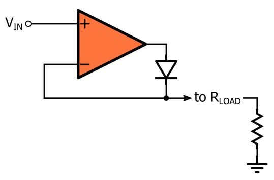
Functionality of a Superdiode
We’ll perform a qualitative analysis of this circuit before we look at simulations. We clearly have a negative feedback connection here, but it’s important to recognize that the op-amp will be operating as both a closed-loop amplifier and an open-loop amplifier.
Let’s assume that we’re using the superdiode to rectify a sine wave. We need some sort of initial condition to start with, so let’s say that the input is negative and the output voltage is at 0 V (this makes sense because the output node is grounded through the load resistance). With this initial condition, the output of the op-amp is saturated at the negative rail and, consequently, the diode is not conducting. With the diode acting like an open circuit, the feedback connection is broken and the op-amp is simply an open-loop amplifier with very high gain.
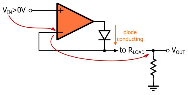
As soon as the input voltage exceeds 0 V, there is a small difference between the inverting input (which is grounded) and the noninverting input. The op-amp’s very high gain causes the output to saturate at the positive rail, and this leads to a forward-biased diode. The diode is now conducting, and thus a negative-feedback path has been established. This means that we can apply the “virtual short” approximation, i.e., the voltage at the noninverting input must equal the voltage at the inverting input. In other words, as soon as the input voltage goes positive, VOUT = VIN.
This condition remains active as long as the input voltage is above 0 V. As soon as VIN goes below ground, the output will try to swing negative, but this will reverse-bias the diode and return the op-amp to the original open-loop state. The output is again pulled down to ground through the load resistor. The result is a near-perfect rectifier: when the input is positive, the output equals the input; when the input is negative, the output is fixed at 0 V.
One thing we need to keep in mind is that the load resistor is an integral part of the circuit; we can’t connect the superdiode’s output directly (i.e., without a pull-down resistor) to a high-impedance input port because when the diode is reverse-biased the op-amp’s inverting input terminal would essentially be floating. Also, the “reverse-biased” superdiode holds the output voltage at the ground potential. In this respect, it is not quite the same as a reverse-biased diode, which acts simply like an open circuit.
Simulations
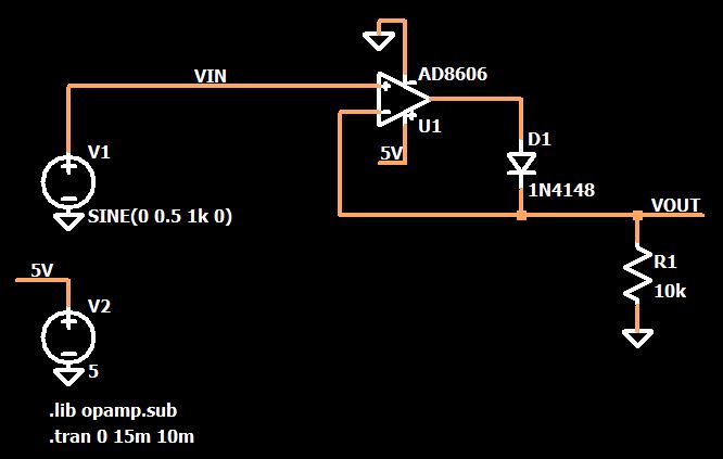
Here is an LTspice implementation of a superdiode:
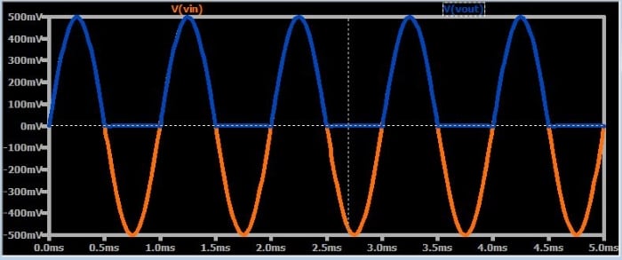
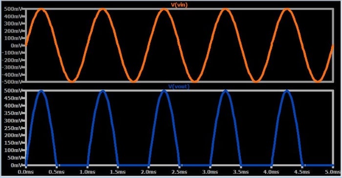
Let’s apply a 0.5 V sine wave. The following plots confirm that the output is a half-wave-rectified version of the input. A typical silicon diode would do nothing here because the input voltage is never high enough to forward-bias the junction, but the superdiode performs marvelously.
What would happen if we tried to rectify a typical 120/240 VAC power-line voltage? Something very bad, to be sure—and herein lies one of the major disadvantages of the superdiode. In order for the superdiode to produce a given output voltage, the op-amp, itself, must generate a voltage that is equal to this output voltage plus a diode drop. In other words, the superdiode’s output voltage is limited by the op-amp’s positive supply rail, and that rail might be much lower than the voltage that you want to rectify.
The superdiode also imposes frequency restrictions. As with any op-amp circuit, the op-amp’s bandwidth influences the high-frequency performance. The following plot shows the superdiode’s (highly unimpressive) rectification of a 1 MHz sinusoid:
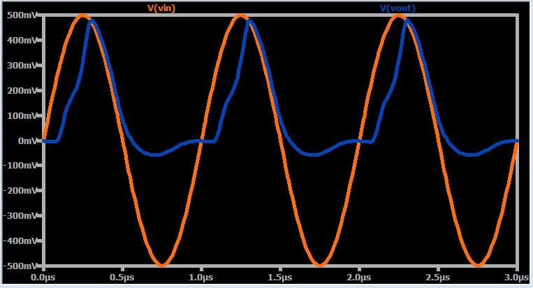
We can see from the downward slope that the op-amp’s frequency response is beginning to contribute some phase shift, but why does the upward-slope portion of the half-cycle look so terrible? The AD8606 has a gain bandwidth product of 9 MHz, so why is the performance so degraded with a 1 MHz signal?
Well, remember that the op-amp is saturated at the negative rail when the input voltage is negative, and it’s a bit of a struggle for the op-amp to recover from this saturated condition. The other problem is that we’re violating the op-amp’s input-voltage range (the AD8606 datasheet indicates that the input voltage should not go below the negative supply rail). I don’t know to what extent the SPICE simulation accurately conveys the effect of these conditions, but we can safely assume that a real-life circuit would also exhibit some type of undesirable behavior under similar circumstances.
Conclusion
We’ve looked at a simple op-amp circuit that can provide “idealized” rectification, i.e., it acts like a diode that becomes forward-biased as soon as the voltage across it exceeds 0 V. In reality, though, this basic superdiode topology is far from ideal because it has significant limitations—bandwidth, saturation, input-voltage range—related to the operational characteristics of the op-amp.
If you want to explore this circuit in greater detail, feel free to download my LTspice schematic by clicking on the orange button.


Good article….
Thank for your information.
It’s really helpful for me to understand electronics.