 Facebook
 Google
 GitHub
 Linkedin
Why the Capacitor in Your Power Supply Filter is Too Big
The job of the capacitor in the output filter of a DC power supply is to maintain a constant DC value by removing as much power ripple as possible. Because these capacitors have a DC value, they are actually storing a lot of energy that never gets used.
All AC-DC converters, whether they are linear supplies or have some kind of switching element to them, require a mechanism to take the varying power on the AC side and produce a constant power on the DC side. Typically a large filter capacitor is used to absorb and store energy when the AC power is higher than what is needed by the DC load and to supply energy to the load when the AC power is lower than what is needed. Figure 1 is a block diagram representation of the power input and power output of a generic AC-DC converter that has an AC line frequency of \[\omega\]. Regardless of the specifics of what is inside the converter block, all converters will have a varying input power and require a constant output power.
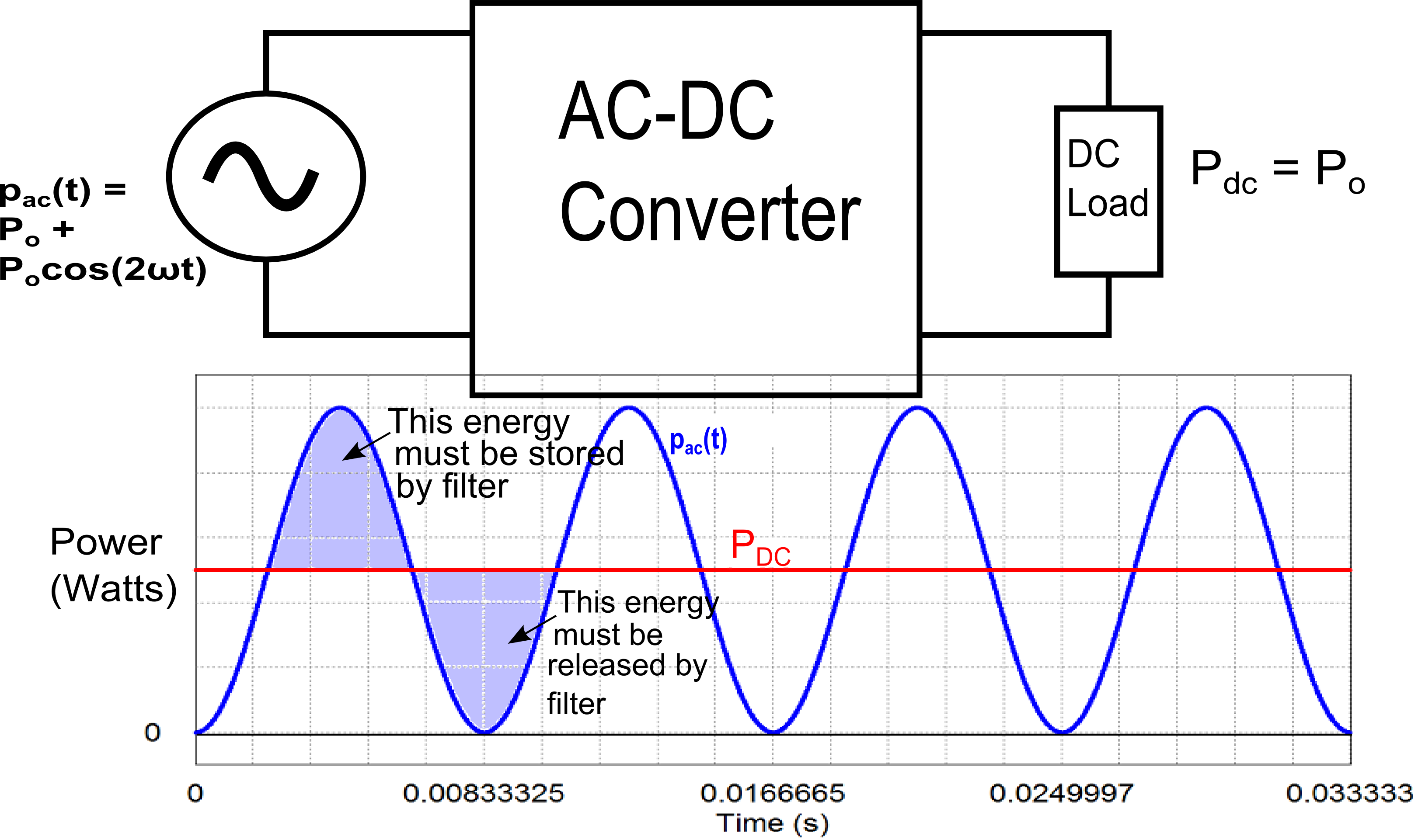
Figure 1. AC-DC Converter Block Diagram with Graph of Power In and Power Out
(Note: This illustration assumes that the power factor at the AC side is 1, so the converter needs to include power factor correction. At the end of this article, you can see how the equation for AC power was derived)
The input power on the AC side is \[p_{ac}(t)=P_{o} + P_{o}cos(2 \omega t)\] while the output power on the DC side is \[P_{o}\]. The ripple power part (\[ P_{o}cos(2 \omega t)\] - which is also highlighted in the graph of the diagram) needs to be eliminated by a filter in the converter. The most common way to implement this filter is to place a large capacitor across the output as shown in Figure 2. This solution is easy and cost effective, but as we will see the filter capacitor stores far more energy than what is actually required for the filtering process.
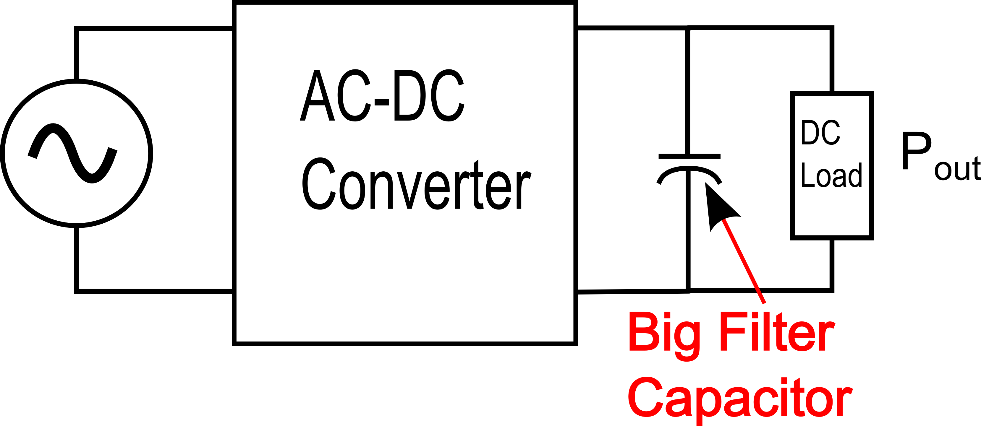
Figure 2. AC-DC Converter With Filter Capacitor at Output
The size of the output filter (i.e., the required capacitance) is determined by how much power must be processed by the system (\[P_{o}\]), the frequency of the AC voltage (\[\omega\] radians per second), the output voltage (\[V_{o}\]) and the peak-to-peak voltage ripple allowable (\[V_{r}\]). The specific equation relating all of these factors to the capacitance is:
\[C_{filt} = \frac{P_{o}}{\omega V_{o} V_{r}}\]
An example system with a line frequency of 60 Hz, an output power of 700W at 390V and a maximum ripple of 8V, requires a capacitance of 595uF. If you were to measure the output voltage of this system, it would look something like this (note that the ripple in this figure is exaggerated for illustration purposes):
.png)
Figure 3. Example Output Voltage with Ripple Voltage
The capacitor is doing its job by absorbing energy from the AC source when AC power provided exceeds the DC power needed and returning energy to the DC load when the AC power provided is less than the DC power needs. The problem is that most of the energy stored in the capacitor is not being used. It is only the small amount of power flow that generates the voltage ripple that is actually being processed by the capacitor. All of that unused stored energy must be in the capacitor, though, to get the voltage of the capacitor up to the voltage required at the output. It's kind of like having a 10,000 liter barrel of water with the spigot placed a few centimeters from the top: the barrel has to be nearly full in order to get any water out, and you can only get water out until it is just below the spigot, then you have to refill it again. All of the water below the spigot is unusable. In the filter capacitor, all of the energy stored--except for the little bit absorbed and released during the voltage ripple--is similarly unusable because you need to keep the output voltage as constant as possible.
If you could design a circuit where you could control the power ripple to a capacitor to match the power ripple of the AC side of the converter and allow the voltage to swing as much as you want, you would have an effective filter that would significantly reduce the double line frequency ripple. The best part of this circuit would be that the capacitor would not have to store any extra energy just to be able to work. The voltage, current and power signals to such a capacitor would look something like this:

Figure 4. Voltage, Current, and Power Waveforms to Hypothetical Filter Circuit
The design of such a circuit is possible. One way that you can create this kind of a circuit is to add a power processing or ripple port that is separate from both the AC input and the DC output. This ripple port would require a storage component (i.e., the capacitor) and a control system to control the power to the port. The port would need to store energy when AC power is too high and release energy when AC power is too low as indicated in figure 4. A block diagram of the ripple port is shown below in figure 5. Since the ripple port is separate from both the input and output ports, neither port imposes any restrictions on the voltage of the ripple port. As you will see, you can reduce the capacitance to an arbitrarily low value by allowing the peak voltage to the capacitor to be really high.
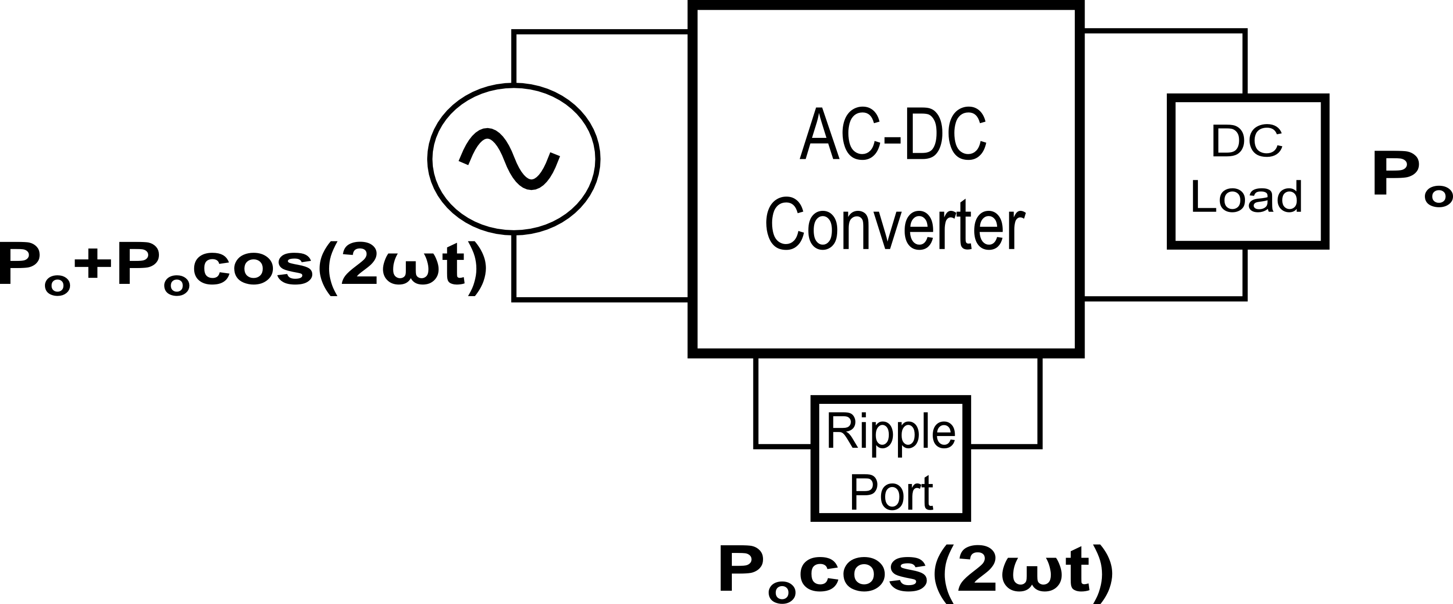
Figure 5. The Ripple Port in an AC-DC Converter
Several different ripple port designs have been investigated and described in the academic literature. One design that stands out for its simplicity as well as its indicated potential in the real world market due to its patent is a design by Krein, et al., discussed here.
The general idea of the design is that we want all of the ripple power (\[P_{o}cos(2\omega t)\]) to flow back and forth to the ripple port capacitor. To get this to happen, we need the ripple power equation to match the equation for the power to a capacitor. The equation for the power to a capacitor in a sinusoidal AC circuit is
\[P_{c}(t)=v_{c}(t)i_{c}(t) = [ V_{c} cos(\omega t + \theta)] \times C\frac{dv_{c}}{dt}\]
It should be noted that \[\theta\] represents the phase shift between the voltage at the AC side of the system and voltage to the ripple port capacitor. The above equation can be simplified using some calculus and trigonometry down to
\[P_{c}(t) = -\omega CV_{c}^{2} \times sin(2\omega t+2\theta )\]
Since we want all of the ripple power to go to the capacitor, we can set the capacitor power equations to be equal to the ripple power equation:
\[P_{o}cos(2\omega t) = \frac{-\omega CV_{c}^{2}}{2} \times sin(2\omega t+2\theta )\]
For the two sides of this equation to be equal, the amplitudes must be the same and the phase shifts must be the same.
First, let's examine the amplitude parts of the above equation; since they must be equal, we get:
\[P_{o}= \frac{\omega CV_{c}^{2}}{2}\]
The two elements that you have control over in this equation are the capacitor and the peak voltage to the capacitor (\[V_{c}\]). Let's go back to the 700W, 390V example we looked at earlier and outline how you would determine the peak voltage and capacitance for the ripple port. First you would decide on a peak voltage for the ripple port. In theory you could pick any voltage you want and the higher the voltage, the lower the capacitance could be, but for safety reasons, you would probably want to pick something less than or equal to the output voltage. In this case, we will pick 300V for the ripple port which is a bit less than the output voltage but high enough that we should get a pretty good reduction of capacitance. Next, you would calculate the required capacitance that would filter the ripple power at 700W. Rearranging the peak power equation for capacitance, gives:
\[C=\frac{2P_{o}}{\omega V_{c}^2}\]
Plugging \[P_{o} = 700W\], \[\omega=2\pi \times 60\], and \[V_{c}=300V\] into the above equation gives us 41uF. This new capacitance is a reduction by a factor of 14.5 times compared to the capacitor in the original design. If we used \[V_{c}=390V\], the capacitance could be reduced even further to 25uF.
We are not done yet, all that we have determined is the peak voltage and capacitance to use. Next, we need to determine the phase shift of the voltage to the capacitor compared to the AC input voltage. To determine the required phase difference, examine the phase shift parts of the power equations and set the phase shift of the power ripple side of the equation equal to the phase shift of the capacitor power side of the equation:
\[-sin(2 \omega t + 2 \theta) = cos(2 \omega t)\]
With some simple trigonometry, this equation can be solved for \[\theta\]:
\[=cos(2 \omega t + 2 \theta + \frac{\pi}{2}) = cos(2 \omega t)\]
\[2 \omega t + 2 \theta + \frac{\pi}{2} = 2 \omega t\]
Finally, if you solve for \[\theta\], which again is the phase difference between the voltage of the AC source and the voltage of the ripple port, you get
\[\theta = -\frac{\pi}{4}\]
Putting the amplitude piece and the phase shift piece together, the bottom line is that if you control the voltage to the ripple port to be
\[v_{c}(t)= \sqrt{\frac{2P_{o}}{\omega C}} sin(\omega t - \frac{\pi}{4})\]
then the ripple port will absorb the double line frequency ripple power in the system.
In our example 700W, 390V system, this means we would need to control the voltage to the ripple port (at maximum power) to be:
\[v_{c}(t)=300sin(\omega t - \frac{\pi}{4})\]
This probably seems like a lot of work considering that the alternative is to simply throw in a big electrolytic capacitor. The problem is that electrolytic capacitors have short life expectancies. Typically, they have shorter life expectancies than any other component in an electronic system, so in systems where decades or more life expectancy is required, electrolytic caps are not a good solution. Film capacitors have a much longer life, but unfortunately are much more expensive than electrolytics for the same capacitance. For example, a quick search of an online electronic component catalog shows that a 600uF, 600V electrolytic capacitor is about $20 while a film capacitor with the same ratings is about $200. A system using this kind of ripple port would be able to cost effectively use a film capacitor instead of an electrolytic because capacitance requirements would be reduced by so much. Of course, before using this kind of system, a cost analysis of the control system for the ripple port would have to be compared to the cost of just using a big (and expensive) film capacitor.
As a final note, the same kind of system can be used for inverters when you need to generate AC voltage from a DC source. The reliability issue with electrolytic capacitors really becomes an issue for photovoltaic panels with built in micro-inverters because these micro-inverters must be warrantied for 20-25 years. That time span is much longer than the expected life of an electrolytic capacitor under any conditions.
Derivation of the AC Line Power Equation
Note that this derivation assumes that power factor is 1 (i.e., voltage and current are in phase with each other)
\[p(t)=v_{ac}(t)i_{ac}(t)\]
\[=V_{ac}cos(\omega t) I_{ac}cos(\omega t)\]
\[=V_{ac}I_{ac}cos^2(\omega t)\]
\[=V_{ac}I_{ac}[\frac{1}{2}(1+cos(2 \omega t))]\]
\[=\frac{V_{ac}I_{ac}}{2} + \frac{V_{ac}I_{ac}}{2}cos(2 \omega t)\]
\[=P_{o} + P_{o}cos(2 \omega t)\] where \[P_{o} = \frac{V_{ac}I_{ac}}{2}\]


To the Author. I can’t read the IEEE article. can you please post enough information so as to elucidate the article. The Math seems meaningless without a circuit diagram
Ripple voltage across the capacitor does not look like that, I’ve never heard of a Ripple port