 Facebook
 Google
 GitHub
 Linkedin
Factors Affecting Inductance
There are four basic factors of inductor construction determining the amount of inductance created. These factors all dictate inductance by affecting how much magnetic field flux will develop for a given amount of magnetic field force (current through the inductor’s wire coil):
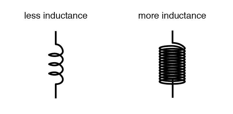
Number of Wire Wraps, or “Turns” in the Coil
All other factors being equal, a greater number of turns of wire in the coil results in greater inductance; fewer turns of wire in the coil results in less inductance.
Explanation: More turns of wire means that the coil will generate a greater amount of magnetic field force (measured in amp-turns!), for a given amount of coil current.
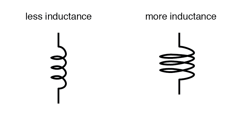
Coil Area
All other factors being equal, greater coil area (as measured looking lengthwise through the coil, at the cross-section of the core) results in greater inductance; less coil area results in less inductance.
Explanation: Greater coil area presents less opposition to the formation of magnetic field flux, for a given amount of field force (amp-turns).
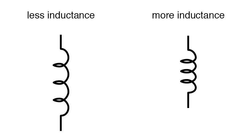
Coil Length
All other factors being equal, the longer the coil’s length, the less inductance; the shorter the coil’s length, the greater the inductance.
Explanation: A longer path for the magnetic field flux to take results in more opposition to the formation of that flux for any given amount of field force (amp-turns).
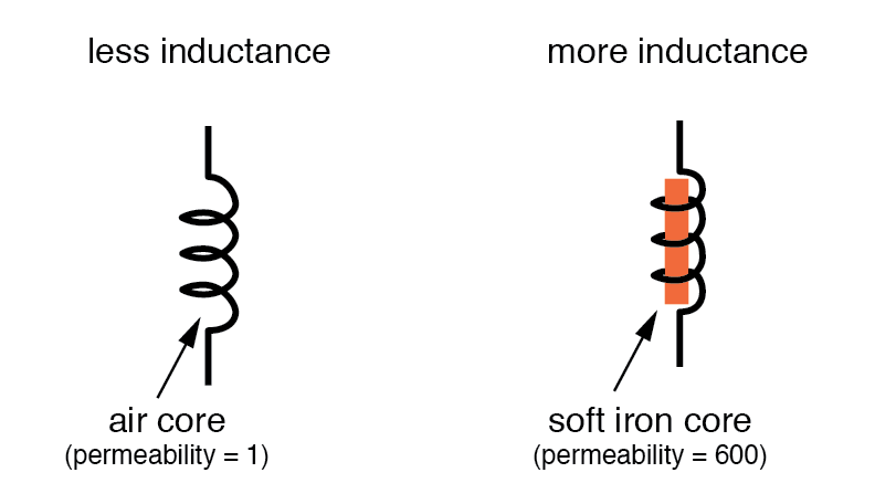
Core Material
All other factors being equal, the greater the magnetic permeability of the core which the coil is wrapped around, the greater the inductance; the less the permeability of the core, the less the inductance.
Explanation: A core material with greater magnetic permeability results in greater magnetic field flux for any given amount of field force (amp-turns).
An approximation of inductance for any coil of wire can be found with this formula:
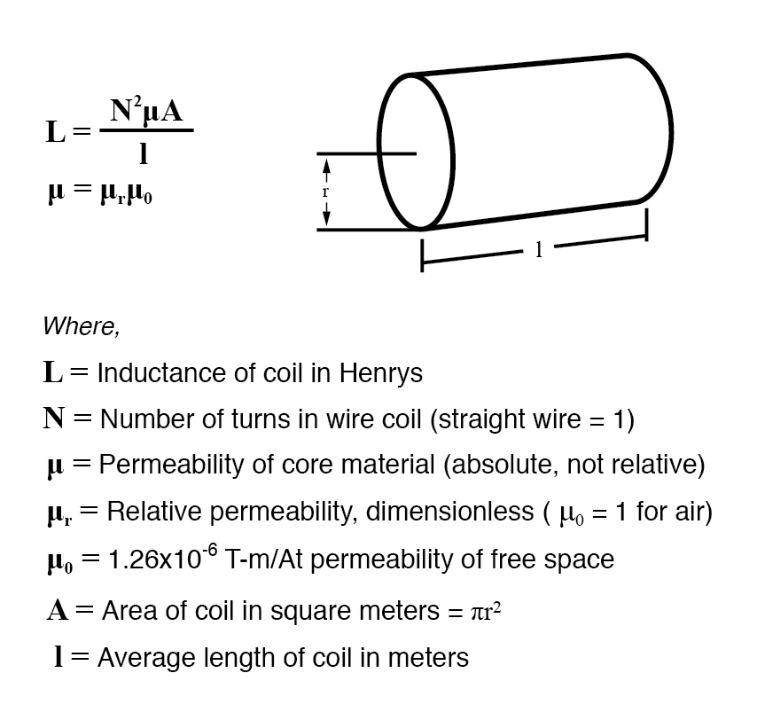
It must be understood that this formula yields approximate figures only. One reason for this is the fact that permeability changes as the field intensity varies (remember the nonlinear “B-H” curves for different materials). Obviously, if permeability (µ) in the equation is unstable, then the inductance (L) will also be unstable to some degree as the current through the coil changes in magnitude.
If the hysteresis of the core material is significant, this will also have strange effects on the inductance of the coil. Inductor designers try to minimize these effects by designing the core in such a way that its flux density never approaches saturation levels, and so the inductor operates in a more linear portion of the B/H curve.
If an inductor is designed so that any one of these factors may be varied at will, its inductance will correspondingly vary. Variable inductors are usually made by providing a way to vary the number of wire turns in use at any given time, or by varying the core material (a sliding core that can be moved in and out of the coil). An example of the former design is shown in this photograph:
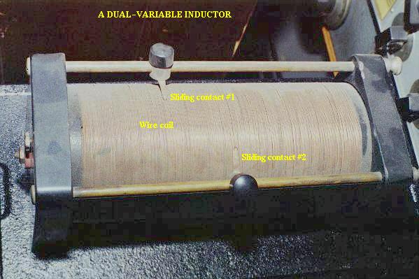
This unit uses sliding copper contacts to tap into the coil at different points along its length. The unit shown happens to be an air-core inductor used in early radio work.
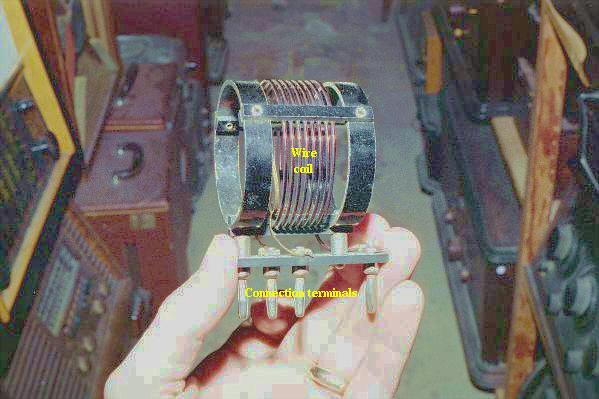
A fixed-value inductor is shown in the next photograph, another antique air-core unit built for radios. The connection terminals can be seen at the bottom, as well as the few turns of relatively thick wire:
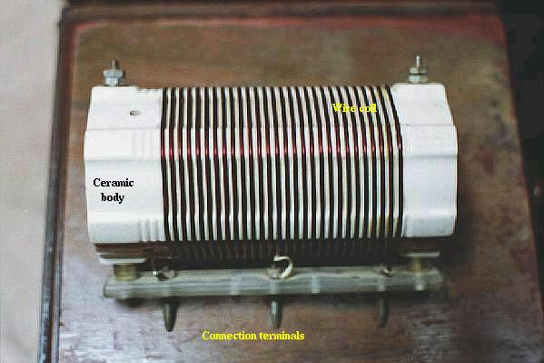
Here is another inductor (of greater inductance value), also intended for radio applications. Its wire coil is wound around a white ceramic tube for greater rigidity:
Inductors can also be made very small for printed circuit board applications. Closely examine the following photograph and see if you can identify two inductors near each other:
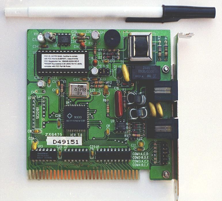
The two inductors on this circuit board are labeled L1 and L2, and they are located to the right-center of the board. Two nearby components are R3 (a resistor) and C< p=""> < sub=”“> (a capacitor). These inductors are called “toroidal” because their wire coils are wound around donut-shaped (“torus”) cores.
Like resistors and capacitors, inductors can be packaged as “surface mount devices” as well. The following photograph shows just how small an inductor can be when packaged as such:
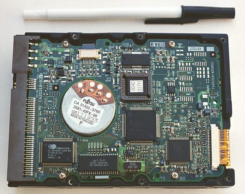
A pair of inductors can be seen on this circuit board, to the right and center, appearing as small black chips with the number “100” printed on both. The upper inductor’s label can be seen printed on the green circuit board as L5. Of course these inductors are very small in inductance value, but it demonstrates just how tiny they can be manufactured to meet certain circuit design needs.
RELATED WORKSHEETS:


Amazing diagrams and explanations, incredible article, very useful