Facebook
 Google
 GitHub
 Linkedin
Network Analysis Techniques
AC Network Analysis
24 questions By Tony R. Kuphaldt
-
Question 4 of 24
Is it safe to close the breaker between these two alternators if their output frequencies are different? Explain why or why not.
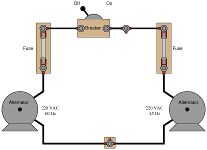
Reveal answerWhen the frequencies of two or more AC voltage sources are different, the phase shift(s) between them are constantly changing.
Follow-up question: what must be done to make the two alternators’ frequencies equal to each other?
Notes:Ask your students to calculate how fast the voltages from these two alternators “roll” in and out of phase with each other.
-
Question 5 of 24
Given the output voltages of the two alternators, it is not safe to close the breaker. Explain why.
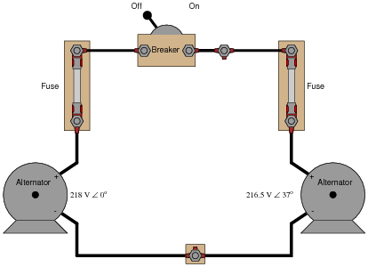
Reveal answerThe greatest problem with closing the breaker is the 37o phase shift between the two alternators’ output voltages.
Follow-up question: what must be done to bring the two alternator voltages into phase with each other?
Challenge question: once the breaker is closed, can the two alternators ever fall out of phase with each other again?
Notes:Discuss the consequences of closing the breaker when there is such a large phase shift between the two alternator output voltages. What will likely happen in the circuit if the breaker is closed under these conditions?
Ask your students whether or not the discrepancy in output voltage (218 VAC versus 216.5 VAC) is of any consequence in closing the breaker. Why is phase shift the only factor mentioned in the answer as a reason not to close the breaker?
This question serves to illustrate alternator theory as well as AC network analysis principles. The “phase-locking” phenomenon of two paralleled alternators is very important for students to understand if they are to do any work related to AC power generation systems.
-
Question 6 of 24
A remote speaker for an audio system is connected to the amplifier by means of a long, 2-conductor cable:
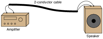
This system may be schematically modeled as an AC voltage source connected to a load resistor:

Suppose we decided to use the 2-conductor cable for more than just conveying an audio (AC) signal - we want to use it to carry DC power as well to energize a small lamp. However, if we were to simply connect the DC power source in parallel with the amplifier output at one end, and the lamp in parallel with the speaker at the other, bad things would happen:
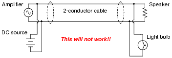
If we were to connect the components together as shown above, the DC power source will likely damage the amplifier by being directly connected to it, the speaker will definitely be damaged by the application of significant DC voltage to its coil, and the light bulb will waste audio power by acting as a second (non-audible) load. Suffice to say, this is a bad idea.
Using inductors and capacitors as “filtering” components, though, we can make this system work:
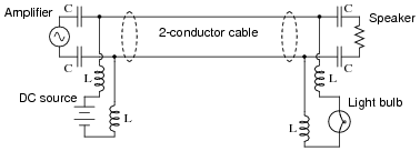
Apply the Superposition Theorem to this circuit to demonstrate that the audio and DC signals will not interfere with each other as they would if directly connected. Assume that the capacitors are of such large value that they present negligible impedance to the audio signal (ZC ≈ 0 Ω) and that the inductors are sufficiently large that they present infinite impedance to the audio signal (ZL ≈ ∞).
Reveal answerAs each source is considered separately, the reactive components ensure each load receives the correct source voltage, with no interference.
Notes:Such “power-plus-data” strategies are made possible by the Superposition Theorem and the linearity of resistors, capacitors, and inductors. If time permits, this would be a good opportunity to discuss “power-line carrier” systems, where high-frequency data is transmitted over power line conductors. The venerable X10 network system is an example for residential power wiring, while power distribution utilities have been using this “PLC” technology (the acronym not to be confused with Programmable Logic Controllers) for decades over high-voltage transmission lines.