
 Facebook
 Google
 GitHub
 Linkedin
AC Electric Circuits
AC Power
47 questions By Tony R. Kuphaldt
-
Question 28 of 47
A very high-power AC electric motor needs to have its power factor measured. You and an electrician are asked to perform this measurement using an oscilloscope. The electrician understands what must be done to measure voltage and current in this dangerous circuit, and you understand how to interpret the oscilloscope’s image to calculate power factor.
It would be impractical to directly measure voltage and current, seeing as how the voltage is 4160 volts AC and the current is in excess of 200 amps. Fortunately, PT (“potential transformer”) and CT (“current transformer”) units are already installed in the motor circuit to facilitate measurements:
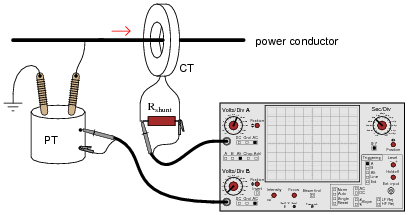
After the electrician helps you safely connect to the PT and CT units, you obtain a Lissajous figure that looks like this:
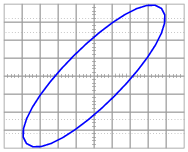
Calculate the power factor of the AC motor from this oscilloscope display.
Reveal answerP.F. ≈ 0.84, lagging (most likely)
Follow-up question: is it possible to determine which waveform is leading or lagging the other from a Lissajous figure? Explain your answer.
Notes:This question provides a good opportunity to review the functions of PT’s and CT’s. Remember that PT’s are transformers with precise step-down ratios used to measure a proportion of the line or phase voltage, which in many cases is safer than measuring the line or phase voltage directly. CT’s are specially-formed transformers which fit around the current-carrying conductor for the purpose of stepping down current (stepping up voltage) so that a low-range ammeter may measure a fraction of the line current.
Students familiar with large electric motors will realize that a 4160 volt motor is going to be three-phase and not single-phase, and that measuring power factor by means of phase shift between voltage and current may be a bit more complicated than what is shown here. This scenario would work for a Y-connected four-wire, three-phase system, but not all three-phase systems are the same!
-
Question 29 of 47
A large electrical load is outfitted with a wattmeter to measure its true power. If the load voltage is 7.2 kV and the load current is 24 amps, calculate the load’s apparent power (S). Calculate the power factor and also the phase angle between voltage and current in the circuit if the wattmeter registers 155 kW at those same voltage and current values.
Draw a “power triangle” for this circuit, graphically showing the relationships between apparent power, true power, and phase angle.
Reveal answerP.F. = 0.897 Θ = 26.23o

Notes:This question provides more practice for students with trigonometry, as well as reinforcing the relationships between S, P, Θ, and power factor.
-
Question 30 of 47
The power factor of this circuit is as low as it can possibly be, 0:
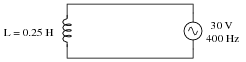
Calculate the apparent, true, and reactive power for this circuit:
- S =
- P =
- Q =
Now, suppose a capacitor is added in parallel with the inductor:

Re-calculate the apparent, true, and reactive power for this circuit with the capacitor connected:
- S =
- P =
- Q =
Reveal answer- Without capacitor
- S = 1.432 VA
- P = 0 W
- Q = 1.432 VAR
- With capacitor
- S = 0.369 VA
- P = 0 W
- Q = 0.369 VAR
Notes:Although the power factor of this circuit is still 0, the total current drawn from the source has been substantially reduced. This is the essence of power factor correction, and the point of this question.


