
 Facebook
 Google
 GitHub
 Linkedin
AC Electric Circuits
AC Power
47 questions By Tony R. Kuphaldt
-
Question 25 of 47
If an electrical device is modeled by fixed values of resistance, inductance, and/or capacitance, it is not difficult to calculate its power factor:
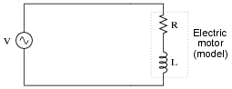
P.F. = R √ R2 + (ωL)2In real life, though, things are not so simple. An electric motor will not come labeled with an ideal-component model expressed in terms of R and L. In fact, that would be impossible, as the resistance R in the circuit model represents the sum total of mechanical work being done by the motor in addition to the energy losses. These variables change depending on how heavily loaded the motor is, meaning that the motor’s power factor will also change with mechanical loading.
However, it may be very important to calculate power factor for electrical loads such as multi-thousand horsepower electric motors. How is this possible to do when we do not know the equivalent circuit configuration or values for such a load? In other words, how do we determine the power factor of a real electrical device as it operates?
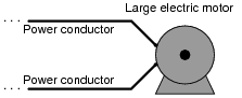
Of course, there do exist special meters to measure true power (wattmeters) and reactive power (“var” meters), as well as power factor directly. Unfortunately, these instruments may not be readily available for our use. What we need is a way to measure power factor using nothing more than standard electrical/electronic test equipment such as multimeters and oscilloscopes. How may we do this?
Hint: remember that the angle Θ of the S-Q-P “power triangle” is the same as the angle in a circuit’s Z-X-R impedance triangle, and also the same as the phase shift angle between total voltage and total current.
Reveal answerUse an oscilloscope to measure the circuit’s Θ (phase shift between voltage and current), and then calculate the power factor from that angle.
Follow-up question #1: explain how you could safely measure currents in the range of hundreds or thousands of amps, and also measure voltages in the range of hundreds or thousands of volts, using an oscilloscope. Bear in mind that you need to simultaneously plot both variables on the oscilloscope in order to measure phase shift!
Follow-up question #2: explain how you could measure either S, Q, or P using a multimeter.
Notes:This is a very practical question! There is a lot to discuss here, including what specific devices to use for measuring voltage and current, what safety precautions to take, how to interpret the oscilloscope’s display, and so on. Of course, one of the most important aspects of this question to discuss is the concept of empirically determining power factor by measuring a circuit’s V/I phase shift.
-
Question 26 of 47
Suppose that a single-phase AC electric motor is performing mechanical work at a rate of 45 horsepower. This equates to 33.57 kW of power, given the equivalence of watts to horsepower (1 HP ≈ 746 W).
Calculate the amount of line current necessary to power this motor if the line voltage is 460 volts, assuming 100% motor efficiency and a power factor of 1.
Now re-calculate the necessary line current for this motor if its power factor drops to 0.65. Assume the same efficiency (100%) and the same amount of mechanical power (45 HP).
What do these calculations indicate about the importance of maintaining a high power factor value in an AC circuit?
Reveal answerP.F. = 1 ; current = 72.98 amps
P.F. = 0.65 ; current = 112.3 amps
Follow-up question: what is the “extra” current in the 0.65 power factor scenario doing, if not contributing to the motor’s mechanical power output?
Notes:Points of discussion for this question should be rather obvious: why is a current of 112.3 amps worse than a current of 72.98 amps when the exact same amount of mechanical work is being done? What circuit components would have to be oversized to accommodate this extra current?
-
Question 27 of 47
An oscilloscope is connected to a low-current AC motor circuit to measure both voltage and current, and plot them against one another as a Lissajous figure:
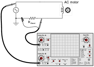
The following Lissajous figure is obtained from this measurement:
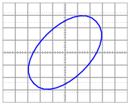
From this figure, calculate the phase angle (Θ) and the power factor for this motor circuit.
Reveal answerΘ ≈ 57o P.F. ≈ 0.54
Follow-up question: is this the only way we could have used the oscilloscope to measure phase shift between voltage and current, or is there another mode of operation besides plotting Lissajous figures?
Notes:Ask your students to explain the function of the resistor Rshunt shown in the schematic diagram. Discuss whether or not this resistor should have a very low or a very high resistance value. Also discuss the placement of the oscilloscope’s ground clip, which is very important in a potentially lethal AC power circuit.


