Facebook
 Google
 GitHub
 Linkedin
AC Electric Circuits
AC Power
47 questions By Tony R. Kuphaldt
-
Question 37 of 47
An inductive AC load consumes 15.2 MW of true power at a voltage of 115 kV and 149.8 amps. If the system frequency is 50 Hz, calculate the following:
- Apparent power (S) =
- Reactive power (Q) =
- Power factor =
- Θ =
- Necessary parallel C size to correct power factor to unity =
Reveal answer- Apparent power (S) = 17.23 MVA
- Reactive power (Q) = 8.107 MVAR
- Power factor = 0.882
- Θ = 28.1o
- Necessary parallel C size to correct power factor to unity = 1.951 μF
Notes:There are multiple methods of solution for this problem, so be sure to have your students present their thoughts and strategies during discussion!
-
Question 38 of 47
A dual-trace oscilloscope is used to measure the phase shift between voltage and current for an inductive AC load:
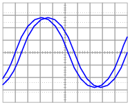
Calculate the following, given a load voltage of 110 volts, a load current of 3.2 amps, and a frequency of 60 Hz:
- Apparent power (S) =
- True power (P) =
- Reactive power (Q) =
- Θ =
- Power factor =
- Necessary parallel C size to correct power factor to unity =
Reveal answer- Apparent power (S) = 352 VA
- True power (P) = 328.2 W
- Reactive power (Q) = 127.2 VAR
- Θ = 21.2o
- Power factor = 0.932
- Necessary parallel C size to correct power factor to unity = 27.9 μF
Follow-up question: identify which waveform represents voltage and which waveform represents current on the oscilloscope display.
Notes:There are multiple methods of solution for this problem, so be sure to have your students present their thoughts and strategies during discussion!
-
Question 39 of 47
Calculate the power factor of this circuit:

Then, calculate the size of the capacitor necessary to “correct” the power factor to a value of 1.0, showing the best location of the capacitor in the circuit.
Reveal answerUncorrected power factor = 0.707, lagging

Follow-up question: when we use capacitors as power factor correction components in an AC power system, the equivalent series resistance (ESR) inside the capacitor becomes a significant factor:

Current through this equivalent series resistance produces heat, and when we’re dealing with MVARs worth of reactive power in high-current circuits, this heat can be substantial unless ESR is held low by special capacitor designs. Describe some possible hazards of excessive ESR for a power factor correction capacitor in a high-current circuit.
Challenge question: the ideal location for power factor correction capacitors is at the load terminals, where the reduction in current will be “felt” by all components in the system except the load itself. However, in real life, power factor correction capacitors are often located at the power plant (the alternator). Why would anyone choose to locate capacitors there? What benefit would they provide at all, in that location?
Notes:Though there are other methods for correcting power factor in AC circuits, the addition of capacitors is perhaps the simplest. Ideally, correction capacitors should be added as close to the load terminals as possible, but in real life they are sometimes located at the power plant (near the alternators). Compare the reduction in conductor currents with the correction capacitor located in different parts of the circuit, and you will see one place in the system where current is reduced no matter where the capacitor is located!
Still, this does not answer the question of why correction capacitors are not always located at the load terminals. Discuss this with your students and see if you can figure out why (hint: what happens when the load’s effective resistance changes, as would happen to an electric motor under varying mechanical loads?).