Facebook
 Google
 GitHub
 Linkedin
Digital Circuits
Basic Logic Gate Troubleshooting
22 questions By Tony R. Kuphaldt
-
Question 16 of 22
A useful test instrument for digital gate circuit troubleshooting is a logic pulser. Explain what one is and give an example of how it is used.
Reveal answerSince most digital electronics textbooks discuss logic pulser’s along with logic probes, I’ll let you do the research here and share with your classmates and instructor what you found!
Notes:Students may wonder how a logic pulser is able to override the output state of any gate it’s connected to. The answer has to do with the brief time that a pulser operates, and also the pulser’s low impedance (compared to the relatively high impedance of the overridden gate output).
-
Question 17 of 22
A technician is using a logic pulser to force the logic state of the wire connecting two of the gates together:
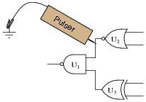
Which gate, or gates, are we testing by placing the pulser in this position? What other instrument(s) would we have to connect to the circuit (and where?) to complete the test? Why does the logic pulser require a ground connection to do its job in this circuit?
Reveal answerIn this location, the pulser is set up to test gate U1. We would have to use a logic probe with “pulse” indication capability on the output of U1 to complete the test.
The pulser requires a ground connection so it may drive current into or out of the circuit under test. Without a ground connection, there would be no complete path for current, and the pulser would not be able to “override” the output state of the NOR gate.
Follow-up question: what logic state should the other input of the NAND gate be in for this test? Explain why.
Notes:The point I am trying to convey with this question is that forcing a gate’s output high or low with a logic pulser tells us nothing about that gate. We use a pulser to override gate outputs in order to test the function of gates receiving that signal. In other words, we use a pulser to test gates “downstream” of where the pulser contacts the circuit.
-
Question 18 of 22
In this circuit, a comparator is set up to detect whether the outside or inside temperature is greater, and turns on a cooling fan when conditions are right. Predict how the operation of this circuit will be affected as a result of the following faults. Consider each fault independently (i.e. one at a time, no multiple faults):

- Comparator U1 output fails low:
- NAND gate U2 output fails low:
- NAND gate U2 output fails high:
- Transistor Q1 fails shorted (drain to source):
- Resistor R2 fails open:
- Thermistor R3 fails open:
- Resistor R4 fails open:
- Solder bridge (short) across thermistor R1:
Reveal answer- Comparator U1 output fails low: Fan never turns on.
- NAND gate U2 output fails low: Fan always remains on.
- NAND gate U2 output fails high: Fan never turns on.
- Transistor Q1 fails shorted (drain to source): Fan always remains on.
- Resistor R2 fails open: Fan never turns on.
- Thermistor R3 fails open: Fan never turns on.
- Resistor R4 fails open: Fan always remains on.
- Solder bridge (short) across thermistor R1: Fan never turns on.
Follow-up question: does Q1 source or sink current? What about Q2?
Notes:Questions like this help students hone their troubleshooting skills by forcing them to think through the consequences of each possibility. This is an essential step in troubleshooting, and it requires a firm understanding of circuit function.