Facebook
 Google
 GitHub
 Linkedin
Analog Integrated Circuits
Basic Operational Amplifiers
18 questions By Tony R. Kuphaldt
-
Question 4 of 18
Many op-amp circuits require a dual or split power supply, consisting of three power terminals: V, -V, and Ground. Draw the necessary connections between the 6-volt batteries in this schematic diagram to provide 12 V, -12 V, and Ground to this op-amp:

Reveal answer
Notes:I encourage your students to learn how to power op-amp circuits with interconnected batteries, because it really helps to build their understanding of what a “split” power supply is, as well as allow them to build functioning op-amp circuits in the absence of a quality benchtop power supply.
-
Question 5 of 18
The 8-pin Dual-Inline-Package (DIP) is a common format in which single and dual operational amplifiers are housed. Shown here are the case outlines for two 8-pin DIPs. Draw the internal op-amp connections for a single op-amp unit, and for a dual op-amp unit:

You will need to research some op-amp datasheets to find this information. Examples of single op-amp chips include the LM741, CA3130, and TL081. Examples of dual op-amp chips include the LM1458 and TL082.
Reveal answer
Notes:Ask your students to reveal their information sources, and what specific models of op-amp they researched.
-
Question 6 of 18
Shown here is a simplified schematic diagram of one of the operational amplifiers inside a TL08x (TL081, TL082, or TL084) op-amp integrated circuit:

Qualitatively determine what will happen to the output voltage (Vout) if the voltage on the noninverting input (Vin ) increases, and the voltage on the inverting input (Vin−) remains the same (all voltages are positive quantities, referenced to -V). Explain what happens at every stage of the op-amp circuit (voltages increasing or decreasing, currents increasing or decreasing) with this change in input voltage.
Reveal answerHere, I’ve labeled a few of the important voltage changes in the circuit, resulting from the increase in non-inverting input voltage (Vin ):
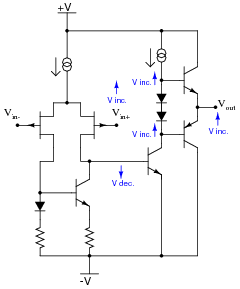
Notes:The answer provided here is minimal. Challenge your students to follow the whole circuit through until the end, qualitatively assessing voltage and current changes.
Incidentally, the strange-looking double-circle symbol is a current source. Ask your students if they were able to find a reference anywhere describing what this symbol means.