Facebook
 Google
 GitHub
 Linkedin
Analog Integrated Circuits
Basic Operational Amplifiers
18 questions By Tony R. Kuphaldt
-
Question 7 of 18
Shown here is a simplified schematic diagram of one of the operational amplifiers inside an LM324 quad op-amp integrated circuit:
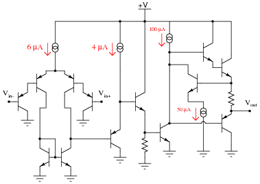
Qualitatively determine what will happen to the output voltage (Vout) if the voltage on the inverting input (Vin−) increases, and the voltage on the non-inverting input (Vin ) remains the same (all voltages are positive quantities, referenced to ground). Explain what happens at every stage of the op-amp circuit (voltages increasing or decreasing, currents increasing or decreasing) with this change in input voltage.
Reveal answerHere, I’ve labeled a few of the important voltage changes in the circuit, resulting from the increase in inverting input voltage (Vin−):
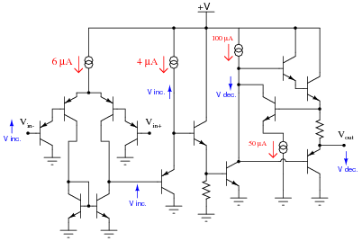
Notes:The answer provided here is minimal. Challenge your students to follow the whole circuit through until the end, qualitatively assessing voltage and current changes.
Incidentally, the strange-looking double-circle symbol is a current source. Ask your students if they were able to find a reference anywhere describing what this symbol means.
-
Question 8 of 18
One of the first popular operational amplifiers was manufactured by Philbrick Researches, and it was called the K2-W. Built with two dual-triode vacuum tubes, its original schematic diagram looked like this:
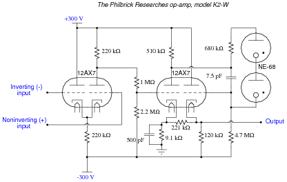
To make this opamp circuit easier for modern students to understand, I’ll substitute equivalent solid-state components for all tubes in the original design:
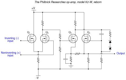
Explain the configuration (common-source, common-drain, or common-gate) of each transistor in the modernized schematic, identifying the function of each in the operational amplifier circuit.
Reveal answerQ1 and Q2 form a differential pair, outputting a signal proportional to the difference in voltage between the two inputs. Q3 is a (bypassed) common-source voltage amplifier, while Q4 is a source-follower (common-drain), providing voltage gain and current gain, respectively.
Notes:The answer as given is incomplete. One could elaborate more on the function of each transistor, and by doing so understand the original amplifier circuit a little better. Explore this circuit with your students, challenging them to follow through the logic of the design, trying to figure out what the designer(s) intended.
This question also provides the opportunity to draw parallels between D-type MOSFET operation and the behavior of triode-type vacuum tubes. As with D-type MOSFETs, triodes were “normally half-on” devices, whose plate-cathode current conduction could be enhanced or depleted by applying voltage to the grid (with respect to the cathode).
-
Question 9 of 18
Determine the functions for as many components as you can in the following schematic diagram of a model 741 operational amplifier:
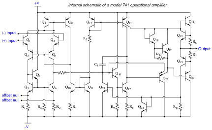
Reveal answerI’ll let you and your classmates have fun with this question!
Notes:Although the model 741 operational amplifier is considered obsolete by many modern standards, it is still a suitable circuit for this kind of exploration with students. Being able to look over a schematic diagram and figure out what the components do is an important troubleshooting skill. The fact that human circuit designers tend to repeat specific circuit elements and “modules” (such as the common-collector amplifier or the current mirror) in their designs rather than invent something completely novel for each design simplifies the task of later interpretation.