Facebook
 Google
 GitHub
 Linkedin
Discrete Semiconductor Devices and Circuits
Bipolar Junction Transistors in Active Mode
23 questions By Tony R. Kuphaldt
-
Question 7 of 23
Conduction of an electric current through the collector terminal of a bipolar junction transistor requires that minority carriers be “injected” into the base region by a base-emitter current. Only after being injected into the base region may these charge carriers be swept toward the collector by the applied voltage between emitter and collector to constitute a collector current:
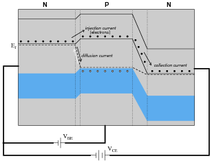
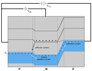
An analogy to help illustrate this is a person tossing flower petals into the air above their head, while a breeze carries the petals horizontally away from them. None of the flower petals may be “swept” away by the breeze until the person releases them into the air, and the velocity of the breeze has no bearing on how many flower petals are swept away from the person, since they must be released from the person’s grip before they can go anywhere.
By referencing either the energy diagram or the flower petal analogy, explain why the collector current for a BJT is strongly influenced by the base current and only weakly influenced by the collector-to-emitter voltage.
Reveal answerThe action of tossing flower petals into the air is analogous to base current injecting charge carriers into the base region of a transistor. The drifting of those tossed petals by the wind is analogous to the sweeping of charge carriers across the base and into the collector by VCE. Like the number of flower petals drifting, the amount of collector current does not depend much on the strength of VCE (the strength of the wind), but rather on the rate of charge carriers injected (the number of petals tossed upward per second).
Notes:This is one of my better analogies for explaining BJT operation, especially for illustrating the why IC is almost independent of VCE. It also helps to explain reverse recovery time for transistors: imagine how long it takes the air to clear of tossed flower petals after you stop tossing them, analogous to latent charge carriers having to be swept out of the base region by VCE after base current stops.
-
Question 8 of 23
Determine the approximate amount of collector current for this transistor circuit, given the following characteristic curve set for the transistor:
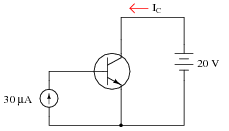
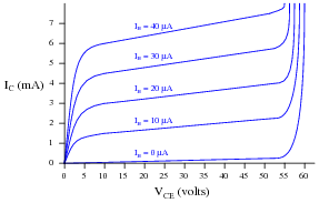
Reveal answerIC ≈ 4.75 mA
Follow-up question: how much will the collector current rise if the voltage source increases to 35 volts?
Notes:This question is nothing more than an exercise in interpreting characteristic curves.
-
Question 9 of 23
The following schematic diagram is of a simple curve tracer circuit, used to plot the current/voltage characteristics of different electronic components on an oscilloscope screen:

The way it works is by applying an AC voltage across the terminals of the device under test, outputting two different voltage signals to the oscilloscope. One signal, driving the horizontal axis of the oscilloscope, represents the voltage across the two terminals of the device. The other signal, driving the vertical axis of the oscilloscope, is the voltage dropped across the shunt resistor, representing current through the device. With the oscilloscope set for “X-Y” mode, the electron beam traces the device’s characteristic curve.
For example, a simple resistor would generate this oscilloscope display:
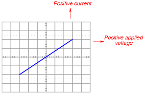
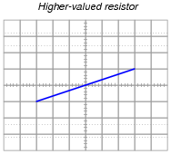
A resistor of greater value (more ohms of resistance) would generate a characteristic plot with a shallower slope, representing less current for the same amount of applied voltage:
Curve tracer circuits find their real value in testing semiconductor components, whose voltage/current behaviors are nonlinear. Take for instance this characteristic curve for an ordinary rectifying diode:
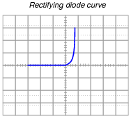
The trace is flat everywhere left of center where the applied voltage is negative, indicating no diode current when it is reverse-biased. To the right of center, though, the trace bends sharply upward, indicating exponential diode current with increasing applied voltage (forward-biased) just as the “diode equation” predicts.
On the following grids, plot the characteristic curve for a diode that is failed shorted, and also for one that is failed open:
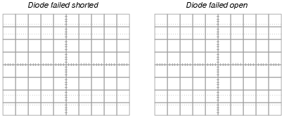
Reveal answer
Notes:Characteristic curves are not the easiest concept for some students to grasp, but they are incredibly informative. Not only can they illustrate the electrical behavior of a nonlinear device, but they can also be used to diagnose otherwise hard-to-measure faults. Letting students figure out what shorted and open curves look like is a good way to open their minds to this diagnostic tool, and to the nature of characteristic curves in general.
Although it is far from obvious, one of the oscilloscope channels will have to be “inverted” in order for the characteristic curve to appear in the correct quadrant(s) of the display. Most dual-trace oscilloscopes have a “channel invert” function that works well for this purpose. If engaging the channel invert function on the oscilloscope flips the wrong axis, you may reverse the connections of the test device to the curve tracer circuit, flipping both axes simultaneously. Between reversing device connections and reversing one channel of the oscilloscope, you can get the curve to plot any way you want it to!