Facebook
 Google
 GitHub
 Linkedin
Discrete Semiconductor Devices and Circuits
BJT Amplifier Troubleshooting
11 questions By Tony R. Kuphaldt
-
Question 10 of 11
Suppose you were troubleshooting the following amplifier circuit, and found the output signal to be symmetrically “clipped” on both the positive and negative peaks:
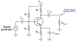

If you knew that this amplifier was a new design, and might not have all its components properly sized, what type of problem would you suspect in the circuit? Please be as specific as possible.
Reveal answerThis amplifier suffers from excessive gain, which may be remedied by changing the value of RC or RE. (I’ll let you determine which way the chosen resistor value must be altered, increase or decrease!)
Of course, changing either of these resistor values will alter the bias (“Q”) point of the amplifier, which may necessitate subsequent changes in the value of either R1 or R2!
Notes:Discuss with your students how to determine the necessary changes in resistor values, based on the determination that the gain is excessive. This is actually very easy to do just by examining the gain formula for a common-emitter amplifier.
Another option to consider here is the addition of a negative feedback signal path to tame the amplifier’s gain. This modification would have the added benefit of improving circuit linearity.
-
Question 11 of 11
This class-B audio power amplifier circuit has a problem: its output is very distorted, resembling half of a sine wave when tested with an input signal from a function generator:

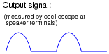
List some of the possible faults in this system, based on the output signal shown by the oscilloscope. Also, determine which components, if any, are known to be good based on the same data:
- Possible faults in the system:
- Fault #1:
- Fault #2:
- Fault #3:
- Components known to be okay in the system:
- Component #1:
- Component #2:
- Component #3:
Reveal answerFirst, realize that we cannot know which half of the push-pull circuit is failed, due to the isolation of the transformer and the resulting uncertainty of polarity. Please note that the lists shown here are not exhaustive.
- Possible faults in the system:
- Fault #1: Transistor Q2 or Q3 failed open
- Fault #2: Resistor R5 or R8 failed open
- Fault #3: Half of transformer primary winding failed open
- Components known to be okay in the system:
- Component #1: Secondary winding of transformer
- Component #2: Resistor R4
- Component #3: Input coupling capacitor C3
Follow-up question #1: suppose that after testing this amplifier on your workbench with a “dummy” load (8 Ω resistor connected to the speaker terminals), you happened to notice that transistor Q2 was slightly warm to the touch, while transistor Q3 was still at room temperature. What would this extra information indicate about the amplifier’s problem?
Follow-up question #2: describe the potential safety hazards involved with touching a power transistor in an operating circuit. If you wished to compare the operating temperature of these two transistors, how could you safely do it?
Notes:The symmetry inherent in push-pull amplifiers makes troubleshooting easier in some respects. As always, though, component-level troubleshooting requires a detailed understanding of component function within the context of the specific circuit being diagnosed. No matter how “simple” the circuit may be, a student will be helpless to troubleshoot it down to the component level unless they understand how and why each component functions.
Giving the clue regarding transistor temperature is important for two reasons. First, it provides more data for students to use in confirming fault possibilities. Second, it underscores the importance of non-electrical data. Efficient troubleshooters make (safe) use of all available data when investigating a problem, and that often requires creative thinking.