Facebook
 Google
 GitHub
 Linkedin
Discrete Semiconductor Devices and Circuits
BJT Amplifier Troubleshooting
11 questions By Tony R. Kuphaldt
-
Question 7 of 11
Study this audio amplifier circuit closely:

Then, determine whether the DC voltage at each test point (VTP1 through VTP6) with respect to ground will increase, decrease, or remain the same for each of the given fault conditions:
Fault VTP1 VTP2 VTP3 VTP4 VTP5 VTP6
R1 failed open Same Same
R2 failed open Same Same
R3 failed open Same Same
R4 failed open Same Same
R5 failed open Same Same
Short between TP2 and ground Same Same
C2 failed shorted Same Same
Q1 collector failed open Same Same
When analyzing component faults, consider only one fault at a time. That is, for each row in the table, you should analyze the circuit as though the only fault in it is the one listed in the far left column of that row.Reveal answerIf the voltage changes to zero, I show 0 in the table. If the increase or decrease is relatively small, I use thin arrows (↑ or ↓). If the change is great, I use thick arrows (⇑ or ⇓).
Fault VTP1 VTP2 VTP3 VTP4 VTP5 VTP6
R1 failed open Same 0 0 ⇑ ⇑ Same
R2 failed open Same ↑ ↑ ⇓ ⇓ Same
R3 failed open Same ↓ ⇓ ⇓ ⇓ Same
R4 failed open Same Same ↑ ⇑ ⇑ Same
R5 failed open Same ≈ Same ≈ Same ↑ ↑ Same
Short between TP2 and ground Same 0 0 ⇑ ⇑ Same
C2 failed shorted Same ↓ 0 ⇓ ⇓ Same
Q1 collector failed open Same ↓ ⇓ ⇑ ⇑ Same
Follow-up question: why don’t test point voltages VTP1 or VTP6 ever change?Notes:I was able to verify specific voltages by building this circuit and faulting each component as described. Although I was not always able to predict the magnitude of the change, I could always predict the direction. This is really all that should be expected of beginning students.
The really important aspect of this question is for students to understand why the test point voltages change as they do. Discuss each fault with your students, and how one can predict the effects just by looking at the circuit.
-
Question 8 of 11
The likelihood that a given component will fail in the “open” mode is quite often not the same as the likelihood that it will fail “shorted.” Based on the research you do and your own personal experience with troubleshooting electronic circuits, determine whether the following components are more likely to fail open or fail shorted (this includes partial, or high-resistance, shorts):
- Resistors:
- Capacitors:
- Inductors:
- Transformers:
- Bipolar transistors:
I encourage you to research information on these devices’ failure modes, as well as glean from your own experiences building and troubleshooting electronic circuits.
Reveal answerRemember that each of these answers merely represents the most likely of the two failure modes, either open or shorted, and that probabilities may shift with operating conditions (i.e. switches may be more prone to failing shorted due to welded contacts if they are routinely abused with excessive current upon closure).
- Resistors: open
- Capacitors: shorted
- Inductors: open or short equally probable
- Transformers: open or short equally probable
- Bipolar transistors: shorted
Follow-up question: When bipolar transistors fail shorted, the short is usually apparent between the collector and emitter terminals (although sometimes all three terminals may register shorted, as though the transistor were nothing more than a junction between three wires). Why do you suppose this is? What is it about the base terminal that makes it less likely to “fuse” with the other terminals?
Notes:Emphasize to your students how a good understanding of common failure modes is important to efficient troubleshooting technique. Knowing which way a particular component is more likely to fail under normal operating conditions enables the troubleshooter to make better judgments when assessing the most probable cause of a system failure.
Of course, proper troubleshooting technique should always reveal the source of trouble, whether or not the troubleshooter has any experience with the failure modes of particular devices. However, possessing a detailed knowledge of failure probabilities allows one to check the most likely sources of trouble first, which generally leads to faster repairs.
An organization known as the Reliability Analysis Center, or RAC, publishes detailed analyses of failure modes for a wide variety of components, electronic as well as non-electronic. They may be contacted at 201 Mill Street, Rome, New York, 13440-6916. Data for this question was gleaned from the RAC’s publication, Part Failure Mode Distributions.
-
Question 9 of 11
Suppose you were troubleshooting the following amplifier circuit, and found the output signal to be “clipped” on the negative peaks:

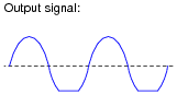
If you knew that this amplifier was a new design, and might not have all its components properly sized, what type of problem would you suspect in the circuit? Please be as specific as possible.
Reveal answerThis amplifier most likely suffers from improper biasing, which may be remedied by changing the value of R1 or R2. (I’ll let you determine which way the chosen resistor value must be altered, increase or decrease!)
Notes:Discuss with your students how to determine whether the bias voltage is too great or too small, based on the observed output waveform. It isn’t difficult to do so long as students understand why biasing exists and how it works.