Facebook
 Google
 GitHub
 Linkedin
Mathematics for Electronics
Calculus for Electric Circuits
30 questions By Tony R. Kuphaldt
-
Question 1 of 30
∫f(x) dx Calculus alert!
Calculus is a branch of mathematics that originated with scientific questions concerning rates of change. The easiest rates of change for most people to understand are those dealing with time. For example, a student watching their savings account dwindle over time as they pay for tuition and other expenses is very concerned with rates of change (dollars per year being spent).
In calculus, we have a special word to describe rates of change: derivative. One of the notations used to express a derivative (rate of change) appears as a fraction. For example, if the variable S represents the amount of money in the student’s savings account and t represents time, the rate of change of dollars over time would be written like this:
dS dtThe following set of figures puts actual numbers to this hypothetical scenario:
- Date: November 20
- Saving account balance (S) = $12,527.33
- Rate of spending ([dS/dt]) = -5,749.01 per year
List some of the equations you have seen in your study of electronics containing derivatives, and explain how rate of change relates to the real-life phenomena described by those equations.
Reveal answerVoltage and current for a capacitor:
i = C dv dtVoltage and current for an inductor:
v = L di dtElectromagnetic induction:
v = N d φ dtI leave it to you to describe how the rate-of-change over time of one variable relates to the other variables in each of the scenarios described by these equations.
Follow-up question: why is the derivative quantity in the student’s savings account example expressed as a negative number? What would a positive [dS/dt] represent in real life?
Challenge question: describe actual circuits you could build to demonstrate each of these equations, so that others could see what it means for one variable’s rate-of-change over time to affect another variable.
Notes:The purpose of this question is to introduce the concept of the derivative to students in ways that are familiar to them. Hopefully the opening scenario of a dwindling savings account is something they can relate to!
A very important aspect of this question is the discussion it will engender between you and your students regarding the relationship between rates of change in the three equations given in the answer. It is very important to your students’ comprehension of this concept to be able to verbally describe how the derivative works in each of these formulae. You may want to have them phrase their responses in realistic terms, as if they were describing how to set up an illustrative experiment for a classroom demonstration.
-
Question 2 of 30
∫f(x) dx Calculus alert!
According to the “Ohm’s Law” formula for a capacitor, capacitor current is proportional to the time-derivative of capacitor voltage:
i = C dv dtAnother way of saying this is to state that the capacitors differentiate voltage with respect to time, and express this time-derivative of voltage as a current.
Suppose we had an oscilloscope capable of directly measuring current, or at least a current-to-voltage converter that we could attach to one of the probe inputs to allow direct measurement of current on one channel. With such an instrument set-up, we could directly plot capacitor voltage and capacitor current together on the same display:
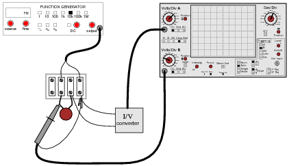
For each of the following voltage waveforms (channel B), plot the corresponding capacitor current waveform (channel A) as it would appear on the oscilloscope screen:
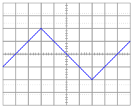
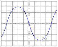
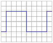
Note: the amplitude of your current plots is arbitrary. What I’m interested in here is the shape of each current waveform!
Reveal answer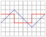


Follow-up question: what electronic device could perform the function of a “current-to-voltage converter” so we could use an oscilloscope to measure capacitor current? Be as specific as you can in your answer.
Notes:Here, I ask students to relate the instantaneous rate-of-change of the voltage waveform to the instantaneous amplitude of the current waveform. Just a conceptual exercise in derivatives.
-
Question 3 of 30
∫f(x) dx Calculus alert!
Potentiometers are very useful devices in the field of robotics, because they allow us to represent the position of a machine part in terms of a voltage. In this particular case, a potentiometer mechanically linked to the joint of a robotic arm represents that arm’s angular position by outputting a corresponding voltage signal:
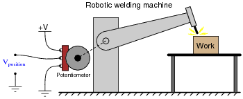
As the robotic arm rotates up and down, the potentiometer wire moves along the resistive strip inside, producing a voltage directly proportional to the arm’s position. A voltmeter connected between the potentiometer wiper and ground will then indicate arm position. A computer with an analog input port connected to the same points will be able to measure, record, and (if also connected to the arm’s motor drive circuits) control the arm’s position.
If we connect the potentiometer’s output to a differentiator circuit, we will obtain another signal representing something else about the robotic arm’s action. What physical variable does the differentiator output signal represent?
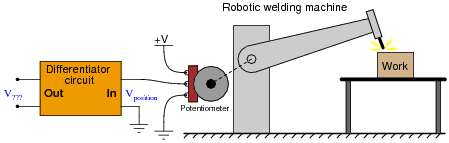
Reveal answerThe differentiator circuit’s output signal represents the angular velocity of the robotic arm, according to the following equation:
v = dx dtWhere,
v = velocity
x = position
t = time
Follow-up question: what type of signal will we obtain if we differentiate the position signal twice (i.e. connect the output of the first differentiator circuit to the input of a second differentiator circuit)?
Notes:This question asks students to relate the concept of time-differentiation to physical motion, as well as giving them a very practical example of how a passive differentiator circuit could be used. In reality, one must be very careful to use differentiator circuits for real-world signals because differentiators tend to amplify high-frequency noise. Since real-world signals are often “noisy,” this leads to a lot of noise in the differentiated signals.