Basic AC-DC Power Supplies

Discrete Semiconductor Devices and Circuits

PDF Version
  • Question 1

    Don’t just sit there! Build something!!

    Learning to mathematically analyze circuits requires much study and practice. Typically, students practice by working through lots of sample problems and checking their answers against those provided by the textbook or the instructor. While this is good, there is a much better way.

    You will learn much more by actually building and analyzing real circuits, letting your test equipment provide the “answers” instead of a book or another person. For successful circuit-building exercises, follow these steps:

    1. Carefully measure and record all component values prior to circuit construction, choosing resistor values high enough to make damage to any active components unlikely.
    2. Draw the schematic diagram for the circuit to be analyzed.
    3. Carefully build this circuit on a breadboard or other convenient medium.
    4. Check the accuracy of the circuit’s construction, following each wire to each connection point, and verifying these elements one-by-one on the diagram.
    5. Mathematically analyze the circuit, solving for all voltage and current values.
    6. Carefully measure all voltages and currents, to verify the accuracy of your analysis.
    7. If there are any substantial errors (greater than a few percent), carefully check your circuit’s construction against the diagram, then carefully re-calculate the values and re-measure.

    When students are first learning about semiconductor devices, and are most likely to damage them by making improper connections in their circuits, I recommend they experiment with large, high-wattage components (1N4001 rectifying diodes, TO-220 or TO-3 case power transistors, etc.), and using dry-cell battery power sources rather than a benchtop power supply. This decreases the likelihood of component damage.

    As usual, avoid very high and very low resistor values, to avoid measurement errors caused by meter “loading” (on the high end) and to avoid transistor burnout (on the low end). I recommend resistors between 1 kΩ and 100 kΩ.

    One way you can save time and reduce the possibility of error is to begin with a very simple circuit and incrementally add components to increase its complexity after each analysis, rather than building a whole new circuit for each practice problem. Another time-saving technique is to re-use the same components in a variety of different circuit configurations. This way, you won’t have to measure any component’s value more than once.

    Reveal answer
  • Question 2

    A technician builds a simple half-wave rectifier circuit for a project, but is surprised to find that the diode keeps failing:


    This comes as a surprise because the diode has a repetitive peak reverse voltage rating of 50 volts, which the technician knows is greater than the peak voltage output by the step-down transformer. However, the technician has overlooked something very important in this circuit design. Explain what the problem is, and how to solve it.

    Reveal answer
  • Question 3

    Diodes and capacitors may be interconnected to form a type of circuit that boosts voltage in the process of rectification. This type of circuit is generally known as a voltage multiplier. Shown here are a few different voltage multiplier circuits:


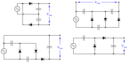
    Determine the degree of voltage multiplication (double, triple, etc.) provided by each circuit.

    Reveal answer
  • Question 4

    Suppose a technician measures the voltage output by an AC-DC power supply circuit:


    The waveform shown by the oscilloscope is mostly DC, with just a little bit of AC “ripple” voltage appearing as a ripple pattern on what would otherwise be a straight, horizontal line. This is quite normal for the output of an AC-DC power supply.

    Suppose we wished to take a closer view of this “ripple” voltage. We want to make the ripples more pronounced on the screen, so that we may better discern their shape. Unfortunately, though, when we decrease the number of volts per division on the “vertical” control knob to magnify the vertical amplification of the oscilloscope, the pattern completely disappears from the screen!

    Explain what the problem is, and how we might correct it so as to be able to magnify the ripple voltage waveform without having it disappear off the oscilloscope screen.

    Reveal answer
  • Question 5

    AC-DC power supply circuits are one of the most common circuit configurations in electronic systems. Though designs may vary, the task of converting AC power to DC power is vital in the functioning of a great many electronic devices.

    Why is this? What is it about this kind of circuit that makes it such a necessary part of many electronic systems?

    Reveal answer
  • Question 6

    Although not a popular design, some power supply circuits are transformerless. Direct rectification of AC line power is a viable option in some applications:


    However, this form of AC-to-DC power conversion has some significant limits. Explain why most power supply circuits utilize a transformer instead of directly rectifying the line power as this circuit does.

    Reveal answer
  • Question 7

    An essential part of an AC-DC power supply circuit is the filter, used to separate the residual AC (called the “ripple” voltage) from the DC voltage prior to output. Here are two simple AC-DC power supply circuits, one without a filter and one with:


    Draw the respective output voltage waveforms of these two power supply circuits (Vunfiltered versus Vfiltered). Also identify the type of filter circuit needed for the task (low pass, high pass, band pass, or band stop), and explain why that type of filter circuit is needed.

    Reveal answer
  • Question 8

    Observe the following two waveforms, as represented on an oscilloscope display measuring output voltage of a filtered power supply:


    If both of these waveforms were measured on the same power supply circuit, at different times, determine which waveform was measured during a period of heavier “loading” (a “heavier” load being defined as a load drawing greater current).

    Reveal answer
  • Question 9

    What does it mean if a power supply has a DC output with 5% ripple?

    Reveal answer
  • Question 10

    What parameters determine the frequency of a power supply’s ripple voltage?

    Reveal answer
  • Question 11

    Suppose a power supply is energized by an AC source of 119 V RMS. The transformer step-down ratio is 8:1, it uses a full-wave bridge rectifier circuit with silicon diodes, and the filter is nothing but a single electrolytic capacitor. Calculate the unloaded DC output voltage for this supply (assume 0.7 volts drop across each diode). Also, write an equation solving for DC output voltage (Vout), given all these parameters.

    Reveal answer
  • Question 12

    What does it mean if a power supply exhibits 2% voltage regulation?

    Reveal answer
  • Question 13

    What will be the consequence of one diode failing open in the bridge rectifier of a single-phase power supply?

    Reveal answer
  • Question 14

    Suppose you suspected a failed-open diode in this power supply circuit. Describe how you could detect its presence without using an oscilloscope:


    Incidentally, the “low voltage AC power supply” is nothing more than a step-down transformer with a center-tapped secondary winding.

    Reveal answer
  • Question 15

    A student learns that a rectifier circuit is often followed by a low-pass filter circuit in an AC-DC power supply to reduce “ripple” voltage on the output. Looking over his notes from AC theory, the student proceeds to build this power supply circuit complete with a low-pass filter at the output:


    While this design will work, there are better filter configurations for this application. Describe the limitations of the circuit shown, and explain how some of the other filters would do a better job.

    Reveal answer
  • Question 16

    Identify the voltages that are supposed to appear between the listed test points:


    1. VTP1−TP2 =
    2. VTP1−TP3 =
    3. VTP2−TP3 =
    4. VTP4−TP5 =
    5. VTP5−TP6 =
    6. VTP7−TP8 =
    7. VTP9−TP10 =

    Assume that the power transformer has a step-down ratio of 9.5:1.

    Reveal answer
  • Question 17

    A technician is troubleshooting a power supply circuit with no DC output voltage. The output voltage is supposed to be 15 volts DC:


    The technician begins making voltage measurements between some of the test points (TP) on the circuit board. What follows is a sequential record of his measurements:

    1. VTP9−TP10 = 0 volts DC
    2. VTP8−TP7 = 0 volts DC
    3. VTP8−TP5 = 0 volts DC
    4. VTP6−TP7 = 0 volts DC
    5. VTP4−TP5 = 0 volts AC
    6. VTP1−TP3 = 0 volts AC
    7. VTP1−TP2 = 116 volts AC

    Based on these measurements, what do you suspect has failed in this supply circuit? Explain your answer. Also, critique this technician’s troubleshooting technique and make your own suggestions for a more efficient pattern of steps.

    Reveal answer
  • Question 18

    A technician is troubleshooting a power supply circuit with no DC output voltage. The output voltage is supposed to be 15 volts DC:


    The technician begins making voltage measurements between some of the test points (TP) on the circuit board. What follows is a sequential record of her measurements:

    1. VTP1−TP2 = 118 volts AC
    2. VTP3−TP2 = 0 volts AC
    3. VTP1−TP3 = 118 volts AC
    4. VTP4−TP5 = 0.5 volts AC
    5. VTP7−TP8 = 1.1 volts DC
    6. VTP9−TP10 = 1.1 volts DC

    Based on these measurements, what do you suspect has failed in this supply circuit? Explain your answer. Also, critique this technician’s troubleshooting technique and make your own suggestions for a more efficient pattern of steps.

    Reveal answer
  • Question 19

    A technician is troubleshooting a power supply circuit with no DC output voltage. The output voltage is supposed to be 15 volts DC:


    The technician begins making voltage measurements between some of the test points (TP) on the circuit board. What follows is a sequential record of his measurements:

    1. VTP9−TP10 = 0 volts DC
    2. VTP1−TP2 = 117 volts AC
    3. VTP1−TP3 = 117 volts AC
    4. VTP5−TP6 = 0 volts AC
    5. VTP7−TP8 = 0.1 volts DC
    6. VTP5−TP4 = 12 volts AC
    7. VTP7−TP6 = 0 volts DC

    Based on these measurements, what do you suspect has failed in this supply circuit? Explain your answer. Also, critique this technician’s troubleshooting technique and make your own suggestions for a more efficient pattern of steps.

    Reveal answer
  • Question 20

    AC-DC power supplies are a cause of harmonic currents in AC power systems, especially large AC-DC power supplies used in motor control circuits and other high-power controls. In this example, I show the waveforms for output voltage and input current for an unloaded AC-DC power supply with a step-down transformer, full-wave rectifier, and capacitive filter circuit (the unfiltered DC voltage waveform is shown as a dashed line for reference):


    As you can see, the input current waveform lags the voltage waveform by 90o, because when the power supply is unloaded, the only input current is the magnetizing current of the transformer’s primary winding.

    With increased loading, the output ripple voltage becomes more pronounced. This also changes the input current waveform significantly, making it non-sinusoidal. Trace the shape of the input current waveform, given the output voltage waveform and magnetizing current waveform (dotted line) shown here:


    The non-filtered DC output waveform is still shown as a dotted line, for reference purposes.

    Reveal answer
  • Question 21

    Power supplies are sometimes equipped with EMI/RFI filters on their inputs, to prevent high-frequency “noise” voltage created within the power supply circuit from getting back to the power source where it might interfere with other powered equipment. This is especially useful for “switching” power supply circuits, where transistors are used to switch power on and off very rapidly in the voltage transformation and regulation process:


    Determine what type of filter circuit this is (LP, HP, BP, or BS), and also determine the inductive and capacitive reactances of its components at 60 Hz, if the inductors are 100 μH each and the capacitors are 0.022 μF each.

    Reveal answer
  • Question 22

    Complete this schematic diagram, turning it into a split (or dual power supply, with three output terminals: V, Ground, and -V:

    Reveal answer
  • Question 23

    Predict how all component voltages and currents in this circuit will be affected as a result of the following faults. Consider each fault independently (i.e. one at a time, no multiple faults):


    Any one diode fails open:
    Transformer secondary winding fails open:
    Inductor L1 fails open:
    Capacitor C1 fails shorted:

    For each of these conditions, explain why the resulting effects will occur.

    Reveal answer
  • Question 24

    Suppose this power supply circuit was working fine for several years, then one day failed to output any DC voltage at all:


    When you open the case of this power supply, you immediately notice the strong odor of burnt components. From this information, determine some likely component faults and explain your reasoning.

    Reveal answer
  • Question 25

    The ripple frequency of a half-wave rectifier circuit powered by 60 Hz AC is measured to be 60 Hz. The ripple frequency of a full-wave rectifier circuit powered by the exact same 60 Hz AC line voltage is measured to be 120 Hz. Explain why the ripple frequency of the full-wave rectifier is twice that of the half-wave rectifier.

    Reveal answer
  • Question 26

    Calculate the approximate DC output voltage of this power supply when it is not loaded:


    Reveal answer
  • Question 27

    Calculate the approximate DC output voltage of this power supply when it is not loaded:


    Reveal answer
  • Question 28

    A simple AC-DC power supply circuit outputs about 6.1 volts DC without a filter capacitor connected, and about 9.3 volts DC with a filter capacitor connected:

    Explain why this is. How can the addition of nothing but a capacitor have such a great effect on the amount of DC voltage output by the circuit?

    Reveal answer
  • Question 29

    A technician is troubleshooting a power supply circuit that outputs substantially less DC voltage than it should. The output voltage is supposed to be 15 volts DC, but instead it is actually outputting less than 8 volts DC:


    The technician measures approximately 18 volts AC (RMS) across the secondary winding of the transformer. Based on this voltage measurement and the knowledge that there is reduced DC output voltage, identify two possible faults that could account for the problem and all measured values in this circuit, and also identify two circuit elements that could not possibly be to blame (i.e. two things that you know must be functioning properly, no matter what else may be faulted). The circuit elements you identify as either possibly faulted or properly functioning can be wires, traces, and connections as well as components. Be as specific as you can in your answers, identifying both the circuit element and the type of fault.

    Circuit elements that are possibly faulted
    1.
    2.
    Circuit elements that must be functioning properly
    1.
    2.
    Reveal answer
  • Question 30

    A technician is troubleshooting a power supply circuit with no DC output voltage. The output voltage is supposed to be 15 volts DC, but instead it is actually outputting nothing at all (zero volts):


    The technician measures 120 volts AC between test points TP1 and TP3. Based on this voltage measurement and the knowledge that there is zero DC output voltage, identify two possible faults that could account for the problem and all measured values in this circuit, and also identify two circuit elements that could not possibly be to blame (i.e. two things that you know must be functioning properly, no matter what else may be faulted). The circuit elements you identify as either possibly faulted or properly functioning can be wires, traces, and connections as well as components. Be as specific as you can in your answers, identifying both the circuit element and the type of fault.

    Circuit elements that are possibly faulted
    1.
    2.
    Circuit elements that must be functioning properly
    1.
    2.
    Reveal answer
  • Question 31

    A common sub-circuit in power supplies of all kinds is an EMI/RFI filter. This LC network is all but “transparent” to the 50 or 60 Hz power line frequency, so that the transformer sees full line voltage at all times:


    If this EMI/RFI filter does nothing to or with the line power, what purpose does it serve?

    Reveal answer
1 Comment
  • R
    Ramesh Nabde November 29, 2021

    i m using power supply for CCTV PTZ Camera with his adaptor rating of 230v AC input & 24V AC Output ,2A load current. what would be the power consumption is their from the main supply line? means is it taking 2 amp from main line of it would be from the adaptor itself?

    Like. Reply