
 Facebook
 Google
 GitHub
 Linkedin
Network Analysis Techniques
DC Branch Current Analysis
7 questions By Tony R. Kuphaldt
-
Question 4 of 7
Describe, step-by-step, the steps required to calculate all currents and voltage drops in a DC network using the Branch Current Method.
Reveal answerThere are several textbooks and other references delineating the steps required in this analysis method. I leave the task of researching these steps to you!
Notes:Students may find slight differences between variations of the “Branch Current” method of analysis described in different references. However, these differences are of no consequence.
-
Question 5 of 7
While the “Branch Current” method may be used to analyze an unbalanced bridge circuit, it requires a lot of calculation! In this circuit, determine how many variables are needed to solve for all currents:
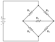
Reveal answerSix variables are required to account for all unique values of current in this circuit (I1 through I6).
Challenge question: draw arrows in this circuit depicting these six currents, and write one KCL equation for each node.
Notes:Ask your students to explain why it is difficult to solve for the currents in a circuit like this using the “Branch Current” method. How many equations would be necessary to solve for the values of six variables?
-
Question 6 of 7
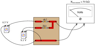
Re-draw the circuit shown here into schematic form, and solve for the voltage drops across the two resistors using the “Branch Current” method:
Reveal answer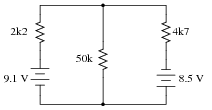
E2200 Ω = 5.713 V
E4700 Ω = 11.89 V
Notes:Be sure to spend time with your students comparing their different solution strategies. With there being so many combinations of ways to draw branch currents and write equations, it is highly unlikely that all students’ work will be identical. The important lesson here is that different variations still lead to the same (correct) results.





its soo easy but complicated at the same time
How am I supposed to solve question 7? At first I disregarded any internal resistances of batter/generator and arrived at incorrect answer. Then howewer I “moved” these internal resistances to corresponding fuses and got the right answer. I’m a bit confused. Is this general method? Can we just pretend our voltage sources are ideal in the sense that there is no internal resistance and just attach serially resistor at the + side (with resistance equal to internal resistance of voltage source)?