Facebook
 Google
 GitHub
 Linkedin
Digital Circuits
Digital-to-Analog Conversion
13 questions By Tony R. Kuphaldt
Page 5
of 5
0 of 13 answers revealed
(0%)
-
Question 13 of 13
This is a digitally-set motor speed controller circuit, using PWM to modulate power to the motor. Predict how the operation of this circuit will be affected as a result of the following faults. Consider each fault independently (i.e. one at a time, no multiple faults):
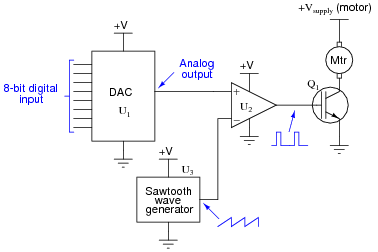
- DAC output fails low (output = 0 volts DC):
- DAC output fails high (output = V):
- IGBT Q1 fails open (collector to emitter):
- Solder bridge (short) between MSB input on U1 and ground:
Reveal answer- DAC output fails low (output = 0 volts DC): Motor will not run.
- DAC output fails high (output = V): Motor runs full speed all the time.
- IGBT Q1 fails open (collector to emitter): Motor will not run.
- Solder bridge (short) between MSB input on U1 and ground: Speeds 0 through 127 work normally, but speeds 128 through 255 just duplicate speeds 0 through 127, respectively.
Notes:Questions like this help students hone their troubleshooting skills by forcing them to think through the consequences of each possibility. This is an essential step in troubleshooting, and it requires a firm understanding of circuit function.
Related Tools:
Published under the terms and conditions of the Creative Commons Attribution License