Facebook
 Google
 GitHub
 Linkedin
Discrete Semiconductor Devices and Circuits
IGFET Amplifiers
3 questions By Tony R. Kuphaldt
-
Question 1 of 3
Don’t just sit there! Build something!! Learning to mathematically analyze circuits requires much study and practice. Typically, students practice by working through lots of sample problems and checking their answers against those provided by the textbook or the instructor. While this is good, there is a much better way.
You will learn much more by actually building and analyzing real circuits, letting your test equipment provide the “answers” instead of a book or another person. For successful circuit-building exercises, follow these steps:
- Carefully measure and record all component values prior to circuit construction, choosing resistor values high enough to make damage to any active components unlikely.
- Draw the schematic diagram for the circuit to be analyzed.
- Carefully build this circuit on a breadboard or other convenient medium.
- Check the accuracy of the circuit’s construction, following each wire to each connection point, and verifying these elements one-by-one on the diagram.
- Mathematically analyze the circuit, solving for all voltage and current values.
- Carefully measure all voltages and currents, to verify the accuracy of your analysis.
- If there are any substantial errors (greater than a few percent), carefully check your circuit’s construction against the diagram, then carefully re-calculate the values and re-measure.
When students are first learning about semiconductor devices, and are most likely to damage them by making improper connections in their circuits, I recommend they experiment with large, high-wattage components (1N4001 rectifying diodes, TO-220 or TO-3 case power transistors, etc.), and using dry-cell battery power sources rather than a benchtop power supply. This decreases the likelihood of component damage.
As usual, avoid very high and very low resistor values, to avoid measurement errors caused by meter “loading” (on the high end) and to avoid transistor burnout (on the low end). I recommend resistors between 1 kΩ and 100 kΩ.
One way you can save time and reduce the possibility of error is to begin with a very simple circuit and incrementally add components to increase its complexity after each analysis, rather than building a whole new circuit for each practice problem. Another time-saving technique is to re-use the same components in a variety of different circuit configurations. This way, you won’t have to measure any component’s value more than once.
Reveal answerLet the electrons themselves give you the answers to your own “practice problems”!
Notes:It has been my experience that students require much practice with circuit analysis to become proficient. To this end, instructors usually provide their students with lots of practice problems to work through, and provide answers for students to check their work against. While this approach makes students proficient in circuit theory, it fails to fully educate them.
Students don’t just need mathematical practice. They also need real, hands-on practice building circuits and using test equipment. So, I suggest the following alternative approach: students should build their own “practice problems” with real components, and try to mathematically predict the various voltage and current values. This way, the mathematical theory “comes alive,” and students gain practical proficiency they wouldn’t gain merely by solving equations.
Another reason for following this method of practice is to teach students scientific method: the process of testing a hypothesis (in this case, mathematical predictions) by performing a real experiment. Students will also develop real troubleshooting skills as they occasionally make circuit construction errors.
Spend a few moments of time with your class to review some of the “rules” for building circuits before they begin. Discuss these issues with your students in the same Socratic manner you would normally discuss the worksheet questions, rather than simply telling them what they should and should not do. I never cease to be amazed at how poorly students grasp instructions when presented in a typical lecture (instructor monologue) format!
A note to those instructors who may complain about the “wasted” time required to have students build real circuits instead of just mathematically analyzing theoretical circuits:
What is the purpose of students taking your course?
If your students will be working with real circuits, then they should learn on real circuits whenever possible. If your goal is to educate theoretical physicists, then stick with abstract analysis, by all means! But most of us plan for our students to do something in the real world with the education we give them. The “wasted” time spent building real circuits will pay huge dividends when it comes time for them to apply their knowledge to practical problems.
Furthermore, having students build their own practice problems teaches them how to perform primary research, thus empowering them to continue their electrical/electronics education autonomously.
In most sciences, realistic experiments are much more difficult and expensive to set up than electrical circuits. Nuclear physics, biology, geology, and chemistry professors would just love to be able to have their students apply advanced mathematics to real experiments posing no safety hazard and costing less than a textbook. They can’t, but you can. Exploit the convenience inherent to your science, and get those students of yours practicing their math on lots of real circuits!
-
Question 2 of 3
A common means of biasing a depletion-type IGFET is called zero biasing. An example circuit is shown below:
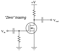
This may appear similar to self-biasing as seen with JFET amplifier circuits, but it is not. Zero biasing only works with IGFET amplifier circuits. Explain why this is so.
Reveal answerThe natural Q-point of a depletion-type IGFET occurs with a gate-to-source voltage of 0 volts. This is very different from either bipolar junction (BJT) or junction field-effect (JFET) transistors.
Follow-up question: will “zero” biasing work with enhancement-mode IGFETs as well? Explain why or why not.
Notes:This question provides students with an opportunity to review IGFET theory, and to differentiate between depletion-mode and enhancement-mode types, which is a subject of much confusion among students new to the topic.
-
Question 3 of 3
One method used to bias enhancement-mode IGFETs is drain-feedback biasing. An example is shown here:
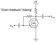
Another method of biasing enhancement-mode IGFETs is the voltage divider technique, which should be familiar to you from your understanding of BJT amplifier circuits:

How do you think the performance of these two differently-biased circuits compare? Assuming they were both biased for the same Q-point, would there be any significant difference(s) in their signal amplifying performance? Why or why not?
Reveal answerOne of these circuits has the potential for much greater voltage gain. I’ll let you determine which one, and more importantly, why.
Notes:This question is a good test of your students’ comprehension of feedback in transistor circuits: what it is, what causes it, and what its effects are.
Ask your students whether they think the technique of drain-feedback biasing would work in a depletion-mode IGFET amplifier circuit.