Facebook
 Google
 GitHub
 Linkedin
Troubleshooting Transistor Circuits
Video Lectures created by Tim Feiegenbaum at North Seattle Community College.
Okay, we're in the final section of chapter 10; Troubleshooting Transistor Circuits.
Troubleshooting strategies discussed in preceding chapters also apply to transistor circuits. Identifying defects in bipolar transistors is accomplished using the following and you need to look at the voltage checks, they are devices called transistor testers that ... which will ... you'll plug a transistor into it and they can test whether it is good or not. Many voltmeters are designed with this option.
Substitution - that is substituting known good components into components that are suspect. Resistance checks - and this would be resistance checks on the circuit to verify the resistances are what they should be and temperature variation can come in because bipolar transistors are subject to variations and data due to temperature changes.
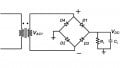
I would encourage you to read through these sections in your textbook. I want to put most of our attention on looking at the extra-sized problems at the end of chapter 10, section five and I had mentioned I was going to do this in one of the earlier sections. It was to do all of the calculations surrounding this particular circuit. Now, this particular circuit is 10-38MSM - this is in your circuits to be used with multi-sim.
DC
I'm going to be doing all the calculations for the circuit. You're not going to be required to do this but there is a listing in the end of this chapter that shows all the voltages that you would expect and I just want to demonstrate that you can go into multi-sim and measure these values but I just want to address how is it these values are actually calculated.
Usually what we do in a circuit like this is we calculate all the DC values and then we go in and calculate the associated AC values. First of all let's look at this. We have 24 volts supplied here and we have a voltage divider right here. Now usually what we would do is we would do a voltage divider and we say two over two plus eight times the 24 volts and that would give us about 4.8 volts and that 4.8 volts would be right here. I'm just going to write this here 4.8 volts and that would be at the base of the transistor.
Since this is a base to emitter here we would expect a 4.7 drop so we would have about 4.1 volts on the emitter. That 4.1 volts would be felt across these two components and if we took 4.1 volts divided by ... what's the resistance here? It was 1,300 – that's only 10 ohms right there and we calculated that current that would be about 3.13 milliamps. That would be the current. It would be DC current flowing through this part of the circuit.
Now recall that the current that is in the emitter flows into the collector. For practical purposes, IE equals IC so we're just going to say that 3.13 milliamps is going to flow up through here and so we would have that 3.13 milliamps – let's write that again - and that would be flowing through the 3.9k. If we took 3.3 milliamps times 3.9K that would be the voltage drop right here and that will be about 12.2 volts. Now recall that we have24 volts right here and so we are going to have a 12.2-volt drop here. If we took 24 and we subtracted 12.2 that would leave us with 11.79 volts at the collector. Now that is a DC value.
Now, this is a pretty close approximation of the DC values that you would measure on this transistor, so because of this voltage divider, we have about 4.8 volts here. We would have about 4.1 here, a 0.7 drop. That would establish a current through these two components that would flow through here. That current would drop a 12.2 volts DC here and then that would ... Since we have 24 volts here we would subtract that out and that would leave about 11.79 volts at the collector of Q1. That is our ... what we would see in terms of DC.
AC
Now I'm going to go to the next screen here and let's look at ... we're going to consider our AC calculations and there is a ... The first one that I ... and remember now we're looking at if we have an AC signal here, what is this AC signal going to experience in this circuit? There are a few values that we need to look at. There's an obscure value that your text doesn't even mention. It's called RE Prime and it's a given formula, it's 0.025 divided by the DC emitter current. Now, in this case, our DC emitter current was 3.13 milliamps and if we did this we would have 0.025 divided by 3.13 milliamps. We'll get about 8 ohms. Now what this RE prime is, that is the AC resistance of the emitter diode. When this AC signal is applied to this base it's going to experience 8 ohms of resistance right here.
Now let's look at the path for the AC input signal. It's going to come in here, it's going to go through the emitter, through this 10 ohms of resistance right here and then down to ground through the capacitor here. Now this component right here in many circles, this is referred to as a swamping component and what it does is it increases the resistance through ... because the AC signal only sees two resistances. It sees the value of RE prime and then it sees the 10 ohms.
Now the problem is that RE prime is subject to the variations in beta and because of that this is not a terribly accurate value. It's in the ballpark but it's not extremely accurate and when we calculate the total gain this will cause it to be a little bit off. Now what we do here, the larger the component that you place here - it tends to swamp out those variations hence the term Swamping Component. The larger this value is, the more stable the amplifier will be, but also the larger this value, the less the gain will be.
The first, what I'll call an obscure value is the value of RE prime and I don't expect you to know that because it's not in your book and we're not going to be doing this level of calculation but I want you to know where these values actually come from - these voltages that you see as normal in your textbook.
Okay, so we've looked at RE prime. The next thing we're going to look at is the voltage that will be ... the AC voltage that will be developed on the collector. Now when the AC voltage is going to be a current development this AC signal is going to be dropped across these two components, this 8 ohms, and this 10 ohms and there's going to be a current that's has developed in the emitter. That current will go through to the emitter and it will develop an AC voltage on the collector.
Now the collector also is going to see a resistance. Now it's going to see ... it's going to see through this cap. It's going to see this resistance over here of 68K but for AC it is going to see this as a common point as well. The AC signal can go this way and it can go this way. The resistance that it experiences is actually the parallel value of 3.9 and 68k. I'm going to put an RC over here; lower case RC is for AC resistance and that will be 3.9k in parallel with the 68k, and that value is going to be 3.68k and that will be our AC collector resistance.
Now there is a little formula that says the gain equals RC over RE prime plus that value for the ... this is going to be the swamping component here and then this would be RE prime right here. If we took that formula we could say 3.68k divided by what will be 18 ohms and if we divide ... and that's going to be the value for A and we could calculate the gain as being 204. What we'll experience here is this signal comes in and this is 10 millibles peak and then the output should be 204 times larger.
Now what you can see here is if the value of this put component is increased - say we increased this to 100 ohms, it'd be ten times greater. By then we would also have ... our gain would be drastically reduced as well because now this would be 108, so our gain would be much lower, but the gain would be much more predictable as well. This is the values that we respect so let's look at ... using ohms law why don't we continue looking at this circuit? Here we have this 10 bolt peak signal. It is applied across the meter and the biasing or the RE here so we would have ... let's see if we were, we could put this at the input.
We have 10 millibles and it is going to be dropped across the 18 ohms and this would result in a current of 555 microamps. Now that 550 micro amps is the AC, remember we had the DC current but this is going to be an AC current. This is actually going to ride on the DC current. This current is going to cause variations in the collector. Now, remember that current is going to go up here. It is AC current so it will be able to go both directions and so if we took this current this 0.5 or excuse me ... 555 microamps time the parallel resistance here and we said it was 3.68k and if we take this current times this voltage we will get 2.04 volts. Now interestingly enough if you take 204 times, the 10 millibles that's the same value that you would get.
This is an overview of where do these values come from. In your textbook the actual measured values they're going to show instead of 2.4. They're going to show 1.8 volts and that has to do with the fact that again this RE prime value, it tends to be ... it varies quite a bit and so this is not an exact in value and again if this is made larger, it will tend to swamp out those variations.
TS
Okay. Next thing I want to do is to look at a couple of troubleshooting problems and in the end of this chapter there's actually five of these and they want you to go to this particular circuit in work bench. Again it is 10 underline 38 and they're going to present - some false and you're going to try to troubleshoot them. Now you only get the odd problems, so I'm going to solve the two even-numbered ones and then you can do the odd ones and you have the answers in your textbook.
Okay. Let's see. Here is ... and again this is the same circuit. This is a 1038 and here is the problem. Number two, DC voltages are normal at all test points in the circuit but there is no AC signal anywhere except that test 0.1. if all the DC is normal. We get about 4.8 here and 4.1 here and something ... what do we have? Let's see. When we did our DC evaluation we had 11.7 on and 11.7 here and it says ... Let's see, okay all the DC is normal but there is no AC signal anywhere except at test 0.1. We see an AC signal here but we should see an AC signal here and we should see one here and actually, we would see a small one right here, but we don't see them. In this case if there is no AC signal here the only component between TP1 and TP2 is right here and so we could conclude that C1 is in fact open.
If you were doing this in an electronic work bench, what you could do is you could simply go in and open the circuit right here or take the cap out and leave the circuit open and this would ... that would simulate this particular problem.
Okay, the next one was test point 4 and it says TP2 measures 4.7. Okay, we've got a 4.7 there. TP3 is 11.7, that looks about normal and TP4 is 4.1 which is about normal. All AC voltages are normal, except there is no AC across R6. We're saying that we have AC here, we have AC here, we have AC here, but we do not have AC here. Well guess what? This is the same fault, except this time C3 is the culprit and in this case it's open or damaged in some way.
Okay. That concludes our little look at troubleshooting and I encourage you to go in and take a look at that circuit. Let's see we looked at test troubleshooting fault number four. We looked at number two. We looked at the AC calculations and again you're not going to have to do these calculations. I'm just showing them for purposes of showing where in the world do these values come from, and then we did the DC calculations and that concludes 10.5.
Related Content