Facebook
 Google
 GitHub
 Linkedin
Linear Transistor Applications
Video Lectures created by Tim Feiegenbaum at North Seattle Community College.
We're continuing in section 10.4 and our focus in this section is on Linear Applications.
Transistors continue to be used in linear applications. Most transistor applications perform interface functions. An interface is used to make the current or voltage levels in one part of the system compatible with another part of the system. Linear IC's consist of several thousand interconnected transistors that perform the desired function.
We're starting out with a current amplifier.
Current Amplifier
The circuit below is being used as a current amp in an industrial computer system. Here we have computer circuits and remember these are going to be putting out zeros and ones, and then we have something called a DAC and this is a Digital to Analog Converter so this would take this digital data and convert it to an analog signal.
Lets' look at our discussion here.
A digital to analog converter converts binary data to an analog format for control of physical quantities such as motor speed, temperature and pressure and these devices are typically referred to as transducers. They are devices that convert physical quantities to electrical quantities and vice-versa. Sometimes they take the quantities and convert it to a voltage, and these devices are used in industrial control.
Here we have a circuit - performing dysfunction.
Q1 is configured as an emitter polar. It will pass the analog value to the external device. The emitter polar will step up a current as a function of data to supply the external device. Here we have the circuit, the binary data converted to analog. The analog data is fed into the transistor and notice this is in the emitter follower configuration, so basically whatever value is here, will be found here in the same phase. The difference is that the output impedances stepped way down and the current is stepped way up. Remember the current that flows through the emitter - most of it goes to the collectors, so only a tiny fraction of that current will actually be felt through the base and this will prevent any unnecessary loading on our digital to analog converter.
Special Amplifier Configurations
There are several special amplifier designs used in many applications that involve the interconnection of multiple transistors. We're going to look at a Darlington pair. We're going to look at differential amps and these, by the way, are the building blocks for the linear integrated circuits. We're going to be looking at something called an Operational Amplifier later in the text or literally, thousands of different configurations are built with amps and the differential amp is the input stage for these devices. Then we'll look at something called a Cascode amplifier.
Darlington Pair
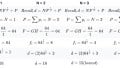
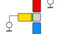
Okay. Here we have a Darlington pair. Let's see, recall the base to collector current, is a function of beta. Now, remember we talked about that. We said beta equals IC over IB and we just ... we've been talking about this but remember that the current that comes up through the middle - only a small fraction goes through the base - most goes to the collector. Since two transistors are being ... are placed together, base ... or emitter to base, the total bail will be a function of beta times beta. If the beta for this transistor was ... Let's just ... I'm going to throw a number here, 141, and the beta for this transistor was 141 and if we've multiplied those out, you'd get about 20k. The current coming through here will be 20,000 times larger than then the current that goes here, so that's quite a change.
Now in this particular device here, your textbook doesn't show it like this. Your textbook actually shows two separate transistors but these are ... this BCX38B actually puts two transistors in one case rather than having them separated. Now what you'll see here if you look carefully at this - you'll see that you come up. As current is supplied through the emitter, it goes to the base and so we would have a current coming out of the base and that would be the function 141 times if that is the beta, smaller than the emitter, and then it's connected to this one and that small, that tiny current goes through here. Then again if the beta is 141 it is again reduced by that fraction.
The current in the base to the emitter will be a function of roughly about 20l if that is, in fact, the case. Now the reason I used that particular number is that the overall current gain can be as high as 20,000 with the Motorola tip 101. Now, this is the Darlington pair that they mentioned in your text which has this particular beta. If you take the square root, this is what you'll get, so the beta reaches roughly 141.
Since volts remains unchanged and current is dramatically stepped up, resistance is very low. Remember that when you had a voltage going into the base and it came off the emitter, the voltage remained almost the same, but current is going to be drastically stepped up. Remember that resistance is inversely proportional to current so as that current is jumped up by this factor, resistance is going to go down by that same factor. This is the ... remember we talked about the emitter follower was used to step down output impedance and so when you're using this kind of device the output impedance will be stepped down just by ... just a huge factor. This would ... output impedes would be very low and this would be suitable for driving low impedance, low as maybe ... we had talked about a speaker; we connected up the speaker here. This type of device is commonly used to drive its final output stages in amplifiers.
Okay. Output is very low impedance which provides high input impedance for the following stage or output and recall. We talked about amplifiers if we had a ... the low output impedance would make for sending the signal to the next stage and if the next stage has a high input impedance then most of that signal will, in fact, be captured.
Differential Amplifiers
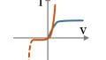
Remember this is the one we talked about, differential amplifiers. It is the input stage of operational amplifiers. Outputs will be equal but opposite. I have a little screenshot here. This is actually from this particular circuit in electronic work bench and this is showing the outputs from Q1 and Q2. You'll notice they are equal but they are opposite.
With no input, the output difference across Q1 and Q2 will be zero volts and so we need to do a little bit looking at the theory of how this actually works. Notice that we have a positive 20 volts up here at the top of the amp and a negative 20 volts down here at the bottom. Now what will happen here is that we have this 20 volts across this component right here and it's about 20 volts. What will end up happening is that since we have our source connected like this effectively, we have a ground here and a ground here. Now we don't have ... it's not a ... this would ground out the AC, but since we have the signal source connected to a ground effectively, it works that way.
The minus 20 volts would mean there would 0.7 drop here, 0.7 drops here and so effectively there are 19.3 volts across this 100k component. Now that will develop a specific current and that current will be split two ways - half of it will go this way, half of it will go this way. Now if these two transistors are identically matched which is a requirement for these, we'll have exactly the same current flowing through here and exactly the same current flowing through here.
Now, what that will result in ... let's pretend that this is about 10 volts on the collector here and we'll say 10 volts on the collector here. Now since these are exactly the same voltage, then if we were to connect and look at ... If we had a component across here and we looked at the voltage across this component then it would be zero because each collector has exactly the same ... The difference would be zero and hence the term differential amplifier. What it's going to do is amplify the difference, so if no input, we have zero out.
Okay, equal amounts of current flow through each transistor. With an input overall current remains the same but now unequally divided resulting in an output. Okay, so with an input, let's look and see what happens with an input. Assume we have an AC input coming in and what is going to happen is that here we have the positive value coming into this transistor. Now what that positive is going to do is it is going to ... the biasing of this transistor is going to be ... If we have a negative voltage down here and now we have a positive here, this ...the forward bias is going to increase and this transistor is going to conduct much harder than this one.
What will happen is that we have this current supplier coming up like so. Since this one is conducting harder more current is going to flow through this than this side and since there's only so much current being supplied, more current will be going here than is here. Now, what's the result of that? Well, if there is more current flowing through this transistor, more current will flow through R3. Now that will drop a larger voltage here resulting in a lower voltage here. As this increases, this voltage will actually be decreasing and that is the phenomenon. We talked about phase and version where you have the input into a transistor, the output is inverted. As current increase is here the actual output on Q1, the voltage will go down because more current is dropped across here; more voltage is dropped on this device.
Now on the other side, remember we had more of that current is going through Q1 and there's less current here. Now the opposite happens here. Because there is less current here less voltage is dropped across R2 making more voltage available here, so this voltage will be increasing. If we're measuring across this component we see this one is decreasing, this one is increasing and what we will measure is the difference. The differential output provides an output when the inputs are different. In this particular device, on this output, we would have a ... there are 180 degrees out of phase with the input and this one it would be actually ... it would be in the same phase as the input. When we first introduced transistors, we mentioned that some amplifiers would invert and there would be situations when you would have a non-inverted output and this is the case where you would have a non-inverted output or the output is in the same phase as the input.
Okay. Continuing in our discussion on the differential amps is the same circuit again. The differential amplifier is fundamental in building blocks for linear integrated circuit. As I mentioned earlier these devices are used as the input stage for these things we call op amps. It removes the need for coupling caps so it can amplify down to very low frequencies including DC. Now you remember that for practical purposes we are at virtually ground as the input. Now since we're at ground there's no DC that's interrupting things so we can send in ... there's no need for a coupling capacitor, so we could send in extremely low frequency. In fact, we can go all the way down to DC if we desire, so there's no need for the coupling caps and dealing with the reactors and things that arise from capacitors. That is a major advantage of a differential amplifier.
DAs are used for amplifying low-level signals which are subject to noise. The amp will reject the noise. This is often referred to as Common Mode Noise. Recall there is no output with no input. Noise will appear on both inputs and will not be amplified since it does not represent a difference. Now typically with noise inputs, for example, 60-hertz noise or dis-atmospheric noise, maybe RF energy or whatever that is in surrounding an application, it will be applied to both inputs. Here we have this noise coming. Let's say the noise is here but the noise is also here. Now recall that the differential amplifier only amplifies the difference. If I have the same input here and the same input here there is no difference on the inputs; the noise does not get amplified. I don't think your text mentioned this but this is often referred to as Common Mode Noise since the noise is common to both inputs and therefore it does not get amplified. This represents a major improvement over the Common Emitter Amp. With the Common Emitter Amp, it is going to amplify signal but it's also going to amplify noise and the differential amplifier will not do that.
Cascode Amplifier
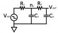
Okay. Then we have the Cascode amplifier. These amplifiers have a very high input impedance since they are using s and they have a very low input capacitance. Now input capacitance tends to shunt high-frequency signals to ground thus reducing gain at age F. Now that's one of the problems with the bipolar transistor, is that there is a capacitance just surrounding the entire transistor and when you begin to send them very, very high-frequency signals that capacitance of the bipolar transistor itself begins to short that signal to ground. This device has a very small input capacitance and as a result, it can be used to amplify high frequency.
Let's take a look brief. Look at this configuration. R2 and R3 provide biasing for Q1 and the numbering I have on these will not be the same as the one in your text. Since I built this with work bench I've got ... so these numbers will apply to these circuits even though it's the same circuit in your text; the numbering of the components is different.
Anyway, R2 and R3 provide the DC biasing for the stat. C5 right here provides an AC ground for Q1. The drain resistance of Q2 sees a low resistance at the source of Q1 right here. Now this results in a low gain for Q2. The high input impedance going in here coupled with the low gain, reduces the capacitance and enables the passing of high-frequency signals. Both J fets in this circuit can be replaced by a dual gate mosfets so both of these components actually can be replaced by a dual gate mosfet. There is a picture of it in your text so that you don't have to have all this, you can just have this dual gate mosfet that serves that function.
Okay. This concludes our brief look at linear amplifiers. We look at the Cascode amp, ideal for high frequencies. We looked at the differential amplifier which amplifies the difference and it is widely used as the input stage in operational amplifiers. We also looked at the Darlington pair which will step down output impedance significantly and actually step up current rather dramatically. Let's see. We looked at a current amplifier. These are used in industrial control; in fact we have an emphasis in our electronics programs specifically addressing the subject of industrial control. I have several quarters actually that address all the different kinds of devices that can be used in industrial control.
This concludes section 10.4 on linear applications.