Facebook
 Google
 GitHub
 Linkedin
MOSFET Amplifiers
Video Lectures created by Tim Feiegenbaum at North Seattle Community College.
Continuing our discussion of MOSFETs in Section 10-3. We're looking at MOSFET Amplifiers. The three basic amplifier configurations discussed for bipolar transistors and JFETS have MOSFET equivalents. We're not going to into all of them but we'll just say that they do have equivalent circuits. Amplifier Biasing. This pertains to amplifiers. Any of the MOSFETs can be used as linear amplifiers. They must be biased so that majority current carriers flow from source to drain. The Gate-source capacitance is biased such that the transistor is operating midway between cutoff and saturation as with all transistor amplifiers.
Remember we had cutoff, we had saturation. This represents basically the on and off positions of the MOSFET. In between those is where we could have linear operation. Remember that when you have linear operation you have an input and the output will have the same shape as the input. If you were allowed to go into saturation or into cutoff, it will no longer retain the same shape as the input.
Once properly biased, an AC signal is applied between gate and source, adding and subtracting from the DC bias. MOSFET amplifiers have 180-degree phase shift between input and output. This is just like we did with bipolar. Most notably, MOSFET amplifiers have extremely high input impedances. Frequently, this is way into the megohms of impedance. This is good because remember when we talked about the input impedance that this allowed the amplifier to capture most of the incoming signal.
Signal Response
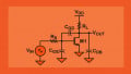
A common source amplifier using an n-channel depletion-mode MOSFET. Here we have an n-channel depletion mode MOSFET with an input signal the current through the MOSFET will vary causing the voltage across RD to vary, thus amplifying the input. This is actually the way that all amplifiers work is that you have an input signal that comes in. The input signal, in this case, goes through the depletion-mode MOSFET. The AC signal will cause the current to vary through the transistor. That current will be passed through here to RD. That changing current will cause this voltage to vary. The output here will be impacted. Thus we will have an amplified signal.
We have a coupling capacitor here. The coupling capacitor is here to simply remove the DC level so that when it goes to the output it is simply pure AC. This is a common-source amplifier. This is using a p-channel enhancement-mode MOSFET. You'll notice the arrow was pointing in the direction that indicates that it is a p-channel. Notice, we have a negative voltage which is characteristics of p-channel devices. Again, we have the same basic behavior and input signal is applied. The current through the enhancement-mode MOSFET is going to vary based on that input signal causing this output to vary and thus we will have our output through the coupling capacitor.
MOSFET Characteristics
Because there are fewer sources of recombination as in bipolar transistors, MOSFETs have every low noise levels associated with them and are ideal for early stages in an amplifier. What does this mean? Because there are fewer sources of recombination, with bipolar we had our material NPN and we had the recombination as electrons passed through the p-material and then through the n-material. Though this seems rather insignificant, this is a source of noise when electrons pass through and they go through the process of recombination.
Recall in a MOSFET type device or with a FET, we go from source to drain. We don't have any recombination. We just have the restrictions that are placed on this material to cause current to vary. The electrons stay in the same material all the way through. There is not recombination. This does reduce noise. This makes them ideal for the early stage in amplifier. One example is that in a television receiver, for example, it has an antenna and when it receives the signal from that antenna it is a very, very, tiny signal. It is very common that MOSFETs are used at that level when the signal is very small to be able to amplify the signal without adding any noise to it.
MOSFET Handling Procedures
This is a very interesting subject. Because of their construction, MOSFETs are extremely sensitive to static voltage charges and must be handled carefully at all times. Otherwise, they will be destroyed. This brings us to the subject of ESD. I suppose I can teach an entire chapter on this subject but I just want to mention it at this point. MOSFETs are what we call ESD sensitive meaning that if they're exposed to electrostatic discharge it can potentially damage the device. They have to be handled very carefully especially when you are repairing a device where a MOSFET needs to be replaced.
ESD stands for Electrostatic Discharge. ESD is developed when two insulators are rubbed together. Some examples that you might recognize is, for example, in a clothes dryer, when clothes are dried and you go and take them out of the dryer, you may have experienced that the popping and the electrostatic voltages as you're pulling the clothes out of the dryer. That's an example of ESD.
Shoes, if you're walking along on a carpet and you're rubbing your feet on the carpet and then you go touch a doorknob. You might experience a little lightning bolt and that would be another example of ESD. Tire rubbing against the pavement. Have you ever been driving a car, you get out of the car, you're standing on the ground and you go to close the door and as you touch the door, you get shocked. The reason for that shock is that if you're driving down the road and you have the rubber tire and the rubber tire is rubbing against the pavement, the rubber tire is an insulator, the asphalt or cement is an insulator. These are essentially rubbing together and actually, there's a separating going on here as well that's causing the static. That static electricity accumulates on the shell of the vehicle. When you step out of the vehicle and you touch to close the door you discharge the static electricity on the shell of the vehicle. Another example is helicopter rotors. As helicopter rotors are spinning around, they can develop tremendous amounts of static electricity.
The static voltage can be very high and is affected by humidity. These are just some ballpark figures. I'm putting these down because these are commonly used values. Like I say, these values would be typical in high humidity areas. If you are in very arid areas like Phoenix, these values could easily double. Rule of thumb here is about 3000 volts of static you can feel it. At about 4000 volts you can hear it. You hear it like with the dryer. Above 5000 volts you can see it. You can actually the little lightning bolt. In your text, it talks about this value being 10 to 11 cables which is very probable if it was in an arid environment.
The point is that this is where you begin to sense these voltages. MOSFETs can be destroyed with as little as 10-100 volts. You will not be able to sense it until it is way above the value where you're looking at potential destruction. At any rate, when handling MOSFETs, it is very important to be aware of the fact that these devices are ESD. Usually, the packaging has symbols on it to indicate that it is ESD sensitive.
Summary of MOSFET Characteristics
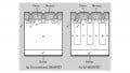
The source and drain terminals connected to opposite ends of the channel material. A depletion-mode MOSFET is one with no gate-source voltage. This is a depletion-mode. Channel current in a depletion-mode MOSFET can be increased or decreased from the no-bias condition. An enhancement-mode MOSFET is cutoff with no gate-source voltage. That's like what we had with bipolar, with no input there was no output. MOSFETS have extremely high input impedances or input resistance. A MOSFET can be used in digital applications by restricting operation to saturation and cutoff. Common-source, drain, and gate are MOSFET amplifier configurations. Common-source amplifiers have 180-degree phase shifts from input to output. This concludes Section 10-3.
Related Content