Facebook
 Google
 GitHub
 Linkedin
Amplifier Basics - Phase Relationships
Video Lectures created by Tim Feiegenbaum at North Seattle Community College.
Continuing in Section 10-1, Addressing Amplifier Basics. The first thing we're going to look at here is Phase Relationships. Signals may or may not be phase shifted as a result of amplifier operations. Amplifiers may be classed as they will be the inverting and the non-inverting. Inverting would mean that here, we had an input, and we would see that our output is out of phase with the input. With the non-inverting, we would have an input and the output would be in the same phase relationship. Input/output phase relationships may be used to characterize amplifier behavior.
This is the amplifier that we had looked at in a couple of lessons back. Note here, the red line is here on the input going over here to the O-scope and then the blue lead from the O-scope is going down here to the output. This is the O-scope representation of those two positions on this schematic and you'll notice that they are 180 degrees out of phase. The red sine wave here is the input. On your screen here in the O-scope capture, it looks like the output is larger than the input, but actually, the output is 147 times larger than the input. Again, the important thing that I'm getting at is that they're out of phase with each other.
Now, there is another type of amplifier configuration called the differential amplifier. We may look at that when we discuss differential amps later. They will utilize two transistors that usually utilize both a negative and a positive voltage. The first transistor in that configuration would be the inverting, but the other transistor would represent the non-inverting outputs. You could have the inverting or the non-inverting if it's in the differential configuration.
Input and Output Resistance
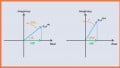
Okay, input and output resistance. This is we often referred to as input and output impedance. Practical amplifiers have input and output resistances that must be considered. For minimal loading effects, we want a source to have a low output resistance and the amplifier to have a high input resistance. Usually, when we evaluate, this is worth looking at voltage. Here we have a signal source and the RO here is indicating the internal impedance of our signal source. When we say RO, we're talking about the output resistance or impedance. Whether you realize this or not, all signal sources will have some type of internal impedance and when they amplify a signal, part of that signal will actually be dropped across the internal resistance of the signal source.
Now, likewise, here we have an amplifier and this is indicating an operational amplifier. Amplifiers have an input impedance and so here we have RI. And I here is for input and R is for resistance or impedance. Now, as a rule, you want the impedance to be very large so you want output impedance to be very small, input impedance to be very large. Here is the reason why.
Let's just throw in a couple of values here of resistances and I'll make them simple so that we can quickly do an evaluation here. We'll say that the output impedance here is 10 ohms and that the input impedance is 90 ohms. Here we have a voltage and we're sending in to this amplifier. If we did a voltage divider here, we could quickly see--let's see if we did 10 over 10 plus 90 and we would find that is 1/10 or 10%. In this particular scenario, 10% of the signal from our signal source would be dropped across the internal impedance of the signal source, and that would leave 90% that would actually get over here to our amplifier and get amplified. That would be desirable that most of our signal is, in fact, getting to the amplifier to the be amplified.
Now, if we reverse this scenario and this was 10 and this was 90, this would not be desirable because now, only 10% of our desired signal is ever getting to the amplifier to be amplified. This would not be good. You want to have a low output impedance and a high input impedance. With these operational amplifiers, a common input impedance is in the vicinity of 2 Mega ohms and they're optimized purposely to make a huge input impedance so that when you send a signal to them, they capture nearly all of the signal that is sent to them from the signal source.
Okay, input and output resistance. Now, for maximum transfer of power--now, notice that we're talking at that time about voltage. Now, we're talking about transfer of power. The output resistance of the driving circuit should be equal to the input resistance of the driven circuit. Here we have--common speaker impedances are 8 ohms and so let's put in a ground here and then we'll send a volt or a connection to our speaker. For maximum transfer of power, it would be desirable that this has an input impedance of 8 ohms. That may be mathematically proven. We're not going to go there, but just as a quick analysis. If we consider that this was down 1 ohm, then we would see that most of the signal would be dropped across the amp. If we increase this to infinity, then we would get all of the voltage but the current would be negligible, and so we would have--again, our power transfer would be small. As I said, they can be proven mathematically but for transfer of power, these should be matched so that half of the power is dropped here and half of the power actually is dropped across the speaker or the load.
Classes of Amplifiers
Okay, classes of amplifiers. Amplifiers may be classed in different categories based on their application or operation and there's a wide use of amplifiers. There are voltage amplifiers, current amplifiers, power amplifiers, impedance matching, and then there are several classes, A, B, AB, C, D amplifiers. There are logarithmic amplifiers. I have a note here. Please see the discussion in your text addressing characteristics and typical applications and there are a number of other amplifiers addressed there. Don't memorize them, but do look at the different characteristics and different applications for amplifiers.
Related Content