Facebook
 Google
 GitHub
 Linkedin
Transistor Biasing (cont)
Video Lectures created by Tim Feiegenbaum at North Seattle Community College.
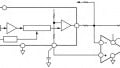
In the previous section, we looked at biasing arranged in this number 1 and 2. Those addressed cutoff and the linear region. We'll be looking at biasing arrangement number 3 in this section. Number 3 addresses forward biasing, the base-emitter, and forward biasing, the collector-base junction. Current is high in all three junctions, mostly in the collector/emitter as previously discussed. This condition is called saturation.
As its name implies, saturation means that the transistor is conducting as hard as it can. Its behavior is much like a short circuit with maximum current flow. The opposite of this would be cut off. We cut off. Both junctions are open and reversed bias, and so we have essentially zero current. In saturation, we have maximum current.
This represents the highest current condition for a transistor. This is the very highest current condition. It represented the voltages often. You might see zero volts on the emitter. You would probably see 0.7 volts on the base and on the collector, 0.1 to 0.2 volts is common. This would represent a forward biasing of both junctions and you would see maximum current flow.
Saturation and cutoff are the conditions that are used in digital circuitry, enhanced microprocessors, etc. Saturation and cutoff would simply--you have the high and the low. With digital circuits, remember you're representing 0 and 1 so we will have a high and a low, and saturation and cutoff would represent those two values.
Biasing Concepts
Important concepts to understand about transistor biasing and characteristics are…Okay, the first one we mentioned, the beta of a transistor. The beta is the relationship of the collector current to the base current, and it is shown as IC/IB. Recall that we mentioned that the beta of a transistor is somewhat unstable. It is also referred to as hFE. Usually, additional biasing is required to cause these to be stable in their basic form. The beta we mentioned one transistor, the 2N39O4. Its beta rating is 100 to 300 and that has to do with the relationship of the base to the collector current and it can be 100 to 300 times larger. That's just the spectrum that it can vary through.
Saturation represents maximum current flow. Cutoff represents no current flow. We also addressed the alpha of a transistor and this is the relationship of the collector current to the emitter current. As a rule, we say that IC equals IE because if you go into measure, you're going to find that the current through the emitter is almost the same. Now, in theory, the way that they operate is that you have current flow. Some of it goes through the base. Most of it goes through the collector. Remember that the amount that goes through the base is limited because the base is lightly doped with just a few holes. In order for current to flow from the emitter to the base, you must have recombination. Only a few electrons were recombined with those holes so we'll have limited flow through the base.
Biasing Requirements
Biasing requirements for various applications, certain conditions must be met for the circuit to operate properly. Here we have an overview. We see we have applications here, the region of the transistor operation and then the biasing requirements for the base-emitter and the collector base. If we're doing digital circuits, the two regions that we're going to be using are saturation and cutoff. For saturation, both junctions must be forward biased. For cutoff, both must be reversed so this is simply the on and this is the off.
For amplifier circuits, we're going to be operating in the linear region and this is where the base-emitter junction must be forward biased and then we're seeing like a contradiction. The collector base junction needed to be reversed. If we were to look at the outputs of a transistor, we would see that when we had the saturation and cutoff, this would represent either a very low value or a very high value. This would come into play for representing zeros and ones in digital circuitry.
For amplifier circuits, we would see our output would be in between those two regions. In linear region, in order for a linear amplifier to be operating correctly, it can never enter into either saturation or cutoff. It has to operate in between because the input must be identical to the output as far as the wave shape is concerned.
This concludes our discussion on biasing and the three conditions that we looked at were saturation, cut off and linear operation.