Facebook
 Google
 GitHub
 Linkedin
Digital Circuits
Microcontroller Principles
20 questions By Tony R. Kuphaldt
-
Question 4 of 20
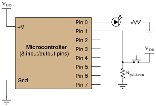
A student decides to build a light-flasher circuit using a microcontroller. The LED is supposed to blink on and off only when the pushbutton switch is depressed. It is supposed to turn off when the switch is released:
Pseudocode listing Declare Pin0 as an output
Declare Pin1 as an input
WHILE Pin1 is HIGH
Set Pin0 HIGH
Pause for 0.5 seconds
Set Pin0 LOW
Pause for 0.5 seconds
ENDWHILE
The LED blinks on and off just fine as long as the pushbutton switch is held when the MCU is powered up or reset. As soon as the switch is released, the LED turns off and never comes back on. If the switch was never pressed during start-up, the LED never comes on! Explain what is happening, and modify the program as necessary to fix this problem.
Reveal answerThe conditional “WHILE” loop needs to be placed inside an unconditional loop:
Pseudocode listing Declare Pin0 as an output
Declare Pin1 as an input
LOOP
WHILE Pin1 is HIGH
Set Pin0 HIGH
Pause for 0.5 seconds
Set Pin0 LOW
Pause for 0.5 seconds
ENDWHILE
ENDLOOP
Follow-up question: what purpose does the resistor Rpulldown serve in the pushbutton circuit?
Notes:The purpose of this question is for students to understand what a “WHILE” loop represents in practical terms: a loop with condition(s). It also contrasts conditional looping against unconditional looping, and shows how both play a part in interactive systems such as this one.
In case you’re wondering why I write in pseudocode, here are a few reasons:
- No prior experience with programming required to understand pseudocode
- It never goes out of style
- Hardware independent
- No syntax errors
If I had decided to showcase code that would actually run in a microcontroller, I would be dooming the question to obsolescence. This way, I can communicate the spirit of the program without being chained to an actual programming standard. The only drawback is that students will have to translate my pseudocode to real code that will actually run on their particular MCU hardware, but that is a problem guaranteed for some regardless of which real programming language I would choose.
Of course, I could have taken the Donald Knuth approach and invented my own (imaginary) hardware and instruction set . . .
-
Question 5 of 20
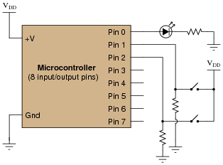
Examine the following schematic diagram and program listing (written in “pseudocode” rather than a formal programming language) to determine what type of basic logic function is being implemented in this microcontroller unit:
Pseudocode listing Declare Pin0 as an output
Declare Pin1 and Pin2 as inputs
LOOP
IF Pin1 is HIGH, set Pin0 HIGH
ELSEIF Pin2 is HIGH, set Pin0 HIGH
ELSE set Pin0 LOW
ENDIF
ENDLOOP
Reveal answerThis microcontroller implements the logical OR function.
Notes:Although this logic function could have been implemented easier and cheaper in hard-wired (gate) logic, the purpose is to get students to think of performing logical operations by a sequenced set of instructions inside a programmable device (the MCU). This is a conceptual leap, basic but very important.
In case you’re wondering why I write in pseudocode, here are a few reasons:
- No prior experience with programming required to understand pseudocode
- It never goes out of style
- Hardware independent
- No syntax errors
If I had decided to showcase code that would actually run in a microcontroller, I would be dooming the question to obsolescence. This way, I can communicate the spirit of the program without being chained to an actual programming standard. The only drawback is that students will have to translate my pseudocode to real code that will actually run on their particular MCU hardware, but that is a problem guaranteed for some regardless of which real programming language I would choose.
Of course, I could have taken the Donald Knuth approach and invented my own (imaginary) hardware and instruction set . . .
-
Question 6 of 20
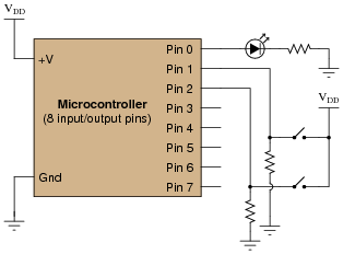
Examine the following schematic diagram and program listing (written in “pseudocode” rather than a formal programming language) to determine what type of basic logic function is being implemented in this microcontroller unit:
Pseudocode listing Declare Pin0 as an output
Declare Pin1 and Pin2 as inputs
LOOP
IF Pin1 is LOW, set Pin0 LOW
ELSEIF Pin2 is LOW, set Pin0 LOW
ELSE set Pin0 HIGH
ENDIF
ENDLOOP
Reveal answerThis microcontroller implements the logical AND function.
Notes:Although this logic function could have been implemented easier and cheaper in hard-wired (gate) logic, the purpose is to get students to think of performing logical operations by a sequenced set of instructions inside a programmable device (the MCU). This is a conceptual leap, basic but very important.
In case you’re wondering why I write in pseudocode, here are a few reasons:
- No prior experience with programming required to understand pseudocode
- It never goes out of style
- Hardware independent
- No syntax errors
If I had decided to showcase code that would actually run in a microcontroller, I would be dooming the question to obsolescence. This way, I can communicate the spirit of the program without being chained to an actual programming standard. The only drawback is that students will have to translate my pseudocode to real code that will actually run on their particular MCU hardware, but that is a problem guaranteed for some regardless of which real programming language I would choose.
Of course, I could have taken the Donald Knuth approach and invented my own (imaginary) hardware and instruction set . . .