Facebook
 Google
 GitHub
 Linkedin
Analog Integrated Circuits
Negative Feedback OpAmp Circuits
21 questions By Tony R. Kuphaldt
-
Question 13 of 21
The purpose of this circuit is to provide a pushbutton-adjustable voltage. Pressing one button causes the output voltage to increase, while pressing the other button causes the output voltage to decrease. When neither button is pressed, the voltage remains stable:
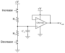
After working just fine for quite a long while, the circuit suddenly fails: now it only outputs zero volts DC all the time.
An experienced technician first checks the power supply voltage to see if it is within normal limits, and it is. Then, the technician checks the voltage across the capacitor. Explain why this is a good test point to check, and what the results of that check would tell the technician about the nature of the fault.
Reveal answerChecking for voltage across the capacitor will tell the technician what voltage the op-amp follower is being “told” to reproduce at the output.
Challenge question: why do you suppose I specify a CA3130 operational amplifier for this particular circuit? What is special about this opamp that qualifies it for the task?
Notes:Knowing where to check for critical signals in a circuit is an important skill, because it usually means the difference between efficiently locating a fault and wasting time. Ask your students to explain in detail the rationale behind checking for voltage across the capacitor, and (again, in detail) what certain voltage measurements at that point would prove about the nature of the fault.
-
Question 14 of 21
A student builds the following regulated AC-DC power supply circuit, but is dissatisfied with its performance:

The voltage regulation is not as good as the student hoped. When loaded, the output voltage “sags” more than the student wants. When the zener diode’s voltage is measured under the same conditions (unloaded output, versus loaded output), its voltage is noted to sag a bit as well. The student realizes that part of the problem here is loading of the zener diode through the transistor. In an effort to improve the voltage regulation of this circuit, the student inserts an opamp “voltage follower” circuit between the zener diode and the transistor:
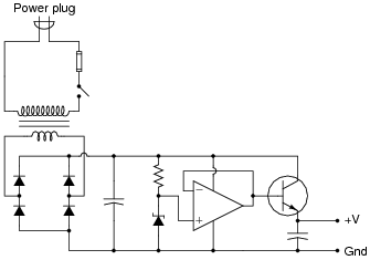
Now the zener diode is effectively isolated from the loading effects of the transistor, and by extension from the output load as well. The opamp simply takes the zener’s voltage and reproduces it at the transistor base, delivering as much current to the transistor as necessary without imposing any additional load on the zener diode.
This modification does indeed improve the circuit’s ability to hold a steady output voltage under changing load conditions, but there is still room for improvement. Another student looks at the modified circuit, and suggests one small change that dramatically improves the voltage regulation:
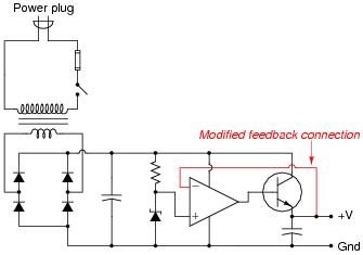
Now the output voltage holds steady at the zener diode’s voltage with almost no “sag” under load! The second student is pleased with the success, but the first student does not understand why this version of the circuit functions any better than previous version. How would you explain this circuit’s improved performance to the first student? How is an understanding of negative feedback essential to being able to comprehend the operation of this circuit?
Reveal answerWith the relocated feedback connection, the opamp now “senses” the load voltage at the output terminals, and is able to correct for any voltage losses in the power transistor.
Follow-up question: the new, improved circuit certainly exhibits better voltage regulation, but it also introduces something that the first student finds surprising: now the output voltage is approximately 0.7 volts greater than it used to be. Explain why.
Notes:This is one of my favorite questions to ask students as they begin to learn how negative feedback works. It is an excellent “litmus test” for comprehension of negative feedback: those students who understand how and why negative feedback works will immediately grasp the significance of the modified feedback connection; those who do not understand negative feedback will fail to grasp why this circuit works at all. Spend as much time as you need discussing this circuit, because it holds the key to student understanding of a great many opamp circuits!
-
Question 15 of 21
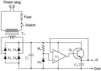
Predict how the operation of this regulated power supply circuit will be affected as a result of the following faults. Consider each fault independently (i.e. one at a time, no multiple faults):
- •
- Transformer T1 primary winding fails open:
- •
- Rectifying diode D3 fails open:
- •
- Rectifying diode D4 fails shorted:
- •
- Resistor R1 fails open:
- •
- Zener diode D5 fails open:
- •
- Operational amplifier U1 fails with output saturated positive:
- •
- Transistor Q1 fails open (collector-to-emitter):
For each of these conditions, explain why the resulting effects will occur.
Reveal answer- Transformer T1 primary winding fails open: Output voltage falls to zero after filter capacitors C1 and C2 discharge.
- Rectifying diode D3 fails open: No effect seen at no load, regulation falters sooner as load gets heavier.
- Rectifying diode D4 fails shorted: Fuse may blow, diode D2 may fail due to overheating (and quickly blow the fuse if it also fails shorted).
- Resistor R1 fails open: Output voltage falls to zero after filter capacitor C2 discharges.
- Zener diode D5 fails open: Output voltage rises to nearly full (unregulated) value.
- Operational amplifier U1 fails with output saturated positive: Output voltage rises to nearly full (unregulated) value.
- Transistor Q1 fails open (collector-to-emitter): Output voltage falls to zero after filter capacitor C2 discharges.
Notes:The purpose of this question is to approach the domain of circuit troubleshooting from a perspective of knowing what the fault is, rather than only knowing what the symptoms are. Although this is not necessarily a realistic perspective, it helps students build the foundational knowledge necessary to diagnose a faulted circuit from empirical data. Questions such as this should be followed (eventually) by other questions asking students to identify likely faults based on measurements.