Facebook
 Google
 GitHub
 Linkedin
Analog Integrated Circuits
Negative Feedback OpAmp Circuits
21 questions By Tony R. Kuphaldt
-
Question 16 of 21
This regulated power supply circuit has a problem. Instead of outputting 15 volts DC (exactly) as it should, it is outputting 0 volts DC to the load:
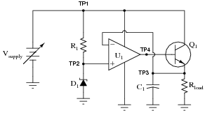
You measure 0.25 volts DC between TP4 and ground, and 20 volts between TP1 and ground, using your voltmeter. From this information, determine at least two independent faults that could cause this particular problem.
Reveal answerPossible faults: (note that this list is not exhaustive)
- Opamp (U1) failed with output saturated negative.
- Zener diode (D1) failed shorted.
- Resistor R1 failed open.
Notes:Ask your students to explain their reasoning, as to why they chose the component faults that they did. Also, ask them to identify any components they think are working properly (beyond a doubt).
-
Question 17 of 21
“Split” or “dual” DC power supplies are essential for powering many types of electronic circuits, especially certain types of operational amplifier circuits. If only a ßingle” DC power supply is not available, a ßplit” power supply may be roughly simulated through the use of a resistive voltage divider:
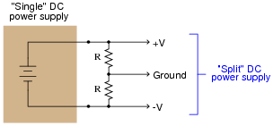
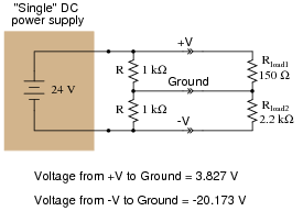
The problem with doing this is loading: if more current is drawn from one of the power supply rails than from the other, the “split” of voltage will become uneven. The only way that V and -V will have the same (absolute) voltage value at the load is if the load impedance is balanced evenly between those rails and ground. This scenario is unlikely. Take for instance this example:
A simple opamp circuit, though, can correct this problem and maintain an even “split” of voltage between V, Ground, and -V:
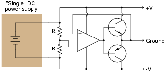
Explain how this circuit works. What function do the two resistors perform? How is negative feedback being used in this circuit?
Reveal answerThe two resistors establish a reference voltage exactly between V and -V, which will be the “Ground” voltage seen by the load. The opamp keeps the actual Ground conductor at that reference potential through negative feedback, driving either transistor as hard as necessary to keep Ground potential centered between V and -V.
Challenge question: if you plan on building this sort of circuit, placing a pair of bypass capacitors across the outputs is highly recommended. Explain why:

Notes:This circuit is not only worthwhile to discuss with your students as an example of negative feedback in action, but it is also practical for them to use as an impromptu power supply “splitter” when only a single supply is available. If you do decide to build this circuit, be careful of the transistors’ power dissipations! Determine the maximum imbalance current to the load (how much current will be drawn through the Ground terminal), and then multiply that current by V (or -V, absolute). This will be the maximum power dissipation value either transistor may have to safely handle.
In response to the challenge question, the wisdom of the bypass capacitors will be evident if a pulsating load (such as a brush-type DC motor) is placed between either “rail” and Ground. The opamp must swing its output back and forth very rapidly to turn on each transistor fast enough to counter dips in voltage caused by the pulsating load. Capacitors naturally resist change in voltage, and so are ideal for mitigating such voltage dips, easing the burden placed on the opamp.
-
Question 18 of 21
Design a passive circuit that will create a “split” ( V/-V) power supply from a single voltage source:
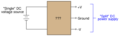
Reveal answerFor low-current applications, the following resistor/capacitor network works remarkably well:

Follow-up question: what design constraints will dictate the sizes of the resistors and capacitors?
Notes:This simple filtered voltage divider circuit works well when the current draws are low, or at least very close to being equal, on the V and -V load rails. It does not work so well for highly asymmetrical loads, or where low quiescent current draw is important (low-power battery circuits, for example). In applications requiring better V/-V voltage stability, an opamp “follower” circuit is recommended after the voltage divider.