Open-Loop OpAmp Circuits

Analog Integrated Circuits

PDF Version
  • Question 1

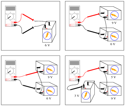
    Determine what the magnitude and polarity of the voltmeter’s indication will be in each case:


    Reveal answer
  • Question 2

    Determine the output voltage polarity of this op-amp (with reference to ground), given the following input conditions:


    Reveal answer
  • Question 3

    Determine the output voltage polarity of this op-amp (with reference to ground), given the following input conditions:


    Reveal answer
  • Question 4

    Determine the output voltage polarity of this op-amp (with reference to ground), given the following input conditions:


    Reveal answer
  • Question 5

    Although the following symbol is generally interpreted as an operational amplifier (“op-amp”), it may also be used to represent a comparator:


    What is the difference between a comparator such as the model LM319, and a true operational amplifier such as the model LM324? Are the two devices interchangeable, or is there any significant difference despite the exact same schematic symbols? Explain your answer.

    Reveal answer
  • Question 6

    In this circuit, a solar cell converts light into voltage for the opamp to “read” on its non-inverting input. The opamp’s inverting input connects to the wiper of a potentiometer. Under what conditions does the LED energize?


    Reveal answer
  • Question 7

    What does the phrase open-loop voltage gain mean with reference to an operational amplifier? For a typical opamp, this gain figure is extremely high. Why is it important that the open-loop voltage gain be high when using an opamp as a comparator?

    Reveal answer
  • Question 8

    A student is operating a simple comparator circuit and documenting the results in a table:


    MMMM MMMM MMMM MMMM
    Vin( ) Vin(−) Vout
    3.00 V 1.45 V 10.5 V
    3.00 V 2.85 V 10.4 V
    3.00 V 3.10 V 1.19 V
    3.00 V 6.75 V 1.20 V

    Vin( ) Vin(−) Vout
    2.36 V 6.50 V 1.20 V
    4.97 V 6.50 V 1.21 V
    7.05 V 6.50 V 10.5 V
    9.28 V 6.50 V 10.4 V

    Vin( ) Vin(−) Vout
    10.4 V 9.87 V 10.6 V
    1.75 V 1.03 V 10.5 V
    0.31 V 1.03 V 10.5 V
    5.50 5.65 V 1.19 V

    One of these output voltage readings is anomalous. In other words, it does not appear to be “correct”. This is very strange, because these figures are real measurements and not predictions! Perplexed, the student approaches the instructor and asks for help. The instructor sees the anomalous voltage reading and says two words: latch-up. With that, the student goes back to research what this phrase means, and what it has to do with the weird output voltage reading.

    Identify which of these output voltage measurements is anomalous, and explain what “latch-up” has to do with it.

    Reveal answer
  • Question 9

    In this automatic cooling fan circuit, a comparator is used to turn a DC motor on and off when the sensed temperature reaches the “setpoint” established by the potentiometer:


    The circuit works just as it is supposed to in turning the motor on and off, but it has a strange problem: the transistor gets warm when the motor is off! Oddly enough, the transistor actually cools down when the motor turns on.

    Describe what you would measure first in troubleshooting this problem. Based on the particular model of op-amp used (a model LM741C), what do you suspect is the problem here?

    Reveal answer
  • Question 10

    Explain the operation of this sound-activated relay circuit:


    Reveal answer
  • Question 11

    Calculate the amount of resistance that the thermistor much reach in order to turn the cooling fan on:


    Reveal answer
  • Question 12

    Predict how the operation of this thermostat circuit (where the cooling fan motor is supposed to turn on when the temperature gets too high) will be affected as a result of the following faults. Consider each fault independently (i.e. one at a time, no multiple faults):


    Cable fails open:
    Comparator U1 fails with output saturated positive:
    Resistor R1 fails open:
    Capacitor C1 fails shorted:
    Transistor Q1 fails shorted (drain-to-source):

    For each of these conditions, explain why the resulting effects will occur.

    Reveal answer
  • Question 13

    Predict how the operation of this thermostat circuit (where the cooling fan motor is supposed to turn on when the temperature gets too high) will be affected as a result of the following faults. Consider each fault independently (i.e. one at a time, no multiple faults):


    Cable fails open:
    Comparator U1 fails with output saturated positive:
    Resistor R1 fails open:
    Cable fails shorted:
    Transistor Q1 fails shorted (drain-to-source):

    For each of these conditions, explain why the resulting effects will occur.

    Reveal answer
  • Question 14

    Predict how the operation of this sound-activated relay circuit will be affected as a result of the following faults. Consider each fault independently (i.e. one at a time, no multiple faults):


    Zener diode D1 fails open:
    Resistor R1 fails open:
    Resistor R2 fails open:
    Microphone voice coil fails open:
    Comparator U1 fails with output saturated positive:
    Diode D3 fails shorted:

    For each of these conditions, explain why the resulting effects will occur.

    Reveal answer
  • Question 15

    Trace the output waveform of this comparator circuit:


    Reveal answer
  • Question 16

    Explain what a window comparator circuit is (sometimes called a window discriminator), and identify at least one practical application for one.

    Reveal answer
  • Question 17

    Photovoltaic solar panels produce the most output power when facing directly into sunlight. To maintain proper positioning, “tracker” systems may be used to orient the panels’ direction as the sun “moves” from east to west across the sky:


    One way to detect the sun’s position relative to the panel is to attach a pair of Light-Dependent Resistors (LDR’s) to the solar panel in such a way that each LDR will receive an equal amount of light only if the panel is pointed directly at the sun:


    Two comparators are used to sense the differential resistance produced by these two LDR’s, and activate a tracking motor to tilt the solar panel on its axis when the differential resistance becomes too great. An “H-drive” transistor switching circuit takes the comparators’ output signals and amplifies them to drive a permanent-magnet DC motor one way or the other:


    In this circuit, what guarantees that the two comparators never output a “high” ( V) voltage simultaneously, thus attempting to move the tracking motor clockwise and counter-clockwise at the same time?

    Reveal answer
  • Question 18

    Predict how the operation of this solar panel tracking circuit (where the tracking motor turns in response to a difference in light sensed by the two photoresistors) will be affected as a result of the following faults. Assuming that the motor spins clockwise when its left terminal is negative and its right terminal is positive (when Q2 and Q3 are both on), specify the direction of rotation (or non-rotation) resulting from each fault. Consider each fault independently (i.e. one at a time, no multiple faults):


    Photoresistor R1 fails open:
    Photoresistor R2 fails open:
    Resistor R4 fails open:
    Resistor R5 fails open:
    Resistor R7 fails open:
    Resistor R10 fails open:
    Transistor Q3 fails open (collector-to-emitter):

    For each of these conditions, explain why the resulting effects will occur.

    Reveal answer
  • Question 19

    Don’t just sit there! Build something!!

    Learning to mathematically analyze circuits requires much study and practice. Typically, students practice by working through lots of sample problems and checking their answers against those provided by the textbook or the instructor. While this is good, there is a much better way.

    You will learn much more by actually building and analyzing real circuits, letting your test equipment provide the “answers” instead of a book or another person. For successful circuit-building exercises, follow these steps:

    1. Carefully measure and record all component values prior to circuit construction.
    2. Draw the schematic diagram for the circuit to be analyzed.
    3. Carefully build this circuit on a breadboard or other convenient medium.
    4. Check the accuracy of the circuit’s construction, following each wire to each connection point, and verifying these elements one-by-one on the diagram.
    5. Mathematically analyze the circuit, solving for all voltage and current values.
    6. Carefully measure all voltages and currents, to verify the accuracy of your analysis.
    7. If there are any substantial errors (greater than a few percent), carefully check your circuit’s construction against the diagram, then carefully re-calculate the values and re-measure.

    Avoid using the model 741 op-amp, unless you want to challenge your circuit design skills. There are more versatile op-amp models commonly available for the beginner. I recommend the LM324 for DC and low-frequency AC circuits, and the TL082 for AC projects involving audio or higher frequencies.

    As usual, avoid very high and very low resistor values, to avoid measurement errors caused by meter “loading”. I recommend resistor values between 1 kΩ and 100 kΩ.

    One way you can save time and reduce the possibility of error is to begin with a very simple circuit and incrementally add components to increase its complexity after each analysis, rather than building a whole new circuit for each practice problem. Another time-saving technique is to re-use the same components in a variety of different circuit configurations. This way, you won’t have to measure any component’s value more than once.

    Reveal answer