Facebook
 Google
 GitHub
 Linkedin
Analog Integrated Circuits
Performance-Based Assessments for Analog Integrated Circuit Competencies
33 questions By Tony R. Kuphaldt
-
Question 28 of 33

Reveal answerUse circuit simulation software to verify your predicted and measured parameter values.
Notes:Use a dual-voltage, regulated power supply to supply power to the opamp. Specify standard resistor values, all between 1 kΩ and 100 kΩ (1k5, 2k2, 2k7, 3k3, 4k7, 5k1, 6k8, 10k, 22k, 33k, 39k 47k, 68k, etc.).
I have had good success using the following values:
- V = 12 volts
- -V = -12 volts
- R1 = R2 = 10 kΩ
- Rpot = 10 kΩ multi-turn
- C1 = C2 = 0.001 μF
- U1 = one-half of LM1458 dual operational amplifier
Note that due to the lack of automatic gain control in this circuit, the potentiometer adjustment is very sensitive! Students will have to finely adjust the multi-turn potentiometer to achieve a good sine wave (meeting the Barkhausen criterion).
An extension of this exercise is to incorporate troubleshooting questions. Whether using this exercise as a performance assessment or simply as a concept-building lab, you might want to follow up your students’ results by asking them to predict the consequences of certain circuit faults.
-
Question 29 of 33
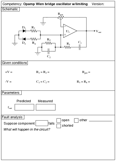
Reveal answerUse circuit simulation software to verify your predicted and measured parameter values.
Notes:Use a dual-voltage, regulated power supply to supply power to the opamp. Specify standard resistor values, all between 1 kΩ and 100 kΩ (1k5, 2k2, 2k7, 3k3, 4k7, 5k1, 6k8, 10k, 22k, 33k, 39k 47k, 68k, etc.).
I have had good success using the following values:
- V = 12 volts
- -V = -12 volts
- R1 = R2 = 10 kΩ
- R3 = R4 = 10 kΩ
- Rpot = 10 kΩ multi-turn
- C1 = C2 = 0.001 μF
- D1 = 1N4148
- D2 = 1N4148
- U1 = one-half of LM1458 dual operational amplifier
With the presence of the amplitude-limiting diodes D1 and D2, the potentiometer adjustment is not nearly as sensitive as without. Try removing both diodes to see what happens when there is no amplitude limiting at all! Students will have to finely adjust the multi-turn potentiometer to achieve a good sine wave (meeting the Barkhausen criterion). With the diodes in place, however, you may adjust the potentiometer for a loop gain just above unity with the only consequence being slight distortion of the waveform rather than severe distortion.
An extension of this exercise is to incorporate troubleshooting questions. Whether using this exercise as a performance assessment or simply as a concept-building lab, you might want to follow up your students’ results by asking them to predict the consequences of certain circuit faults.
-
Question 30 of 33

Reveal answerUse circuit simulation software to verify your predicted and measured parameter values.
Notes:Use a dual-voltage, regulated power supply to supply power to the opamp. Specify standard resistor values, all between 1 kΩ and 100 kΩ (1k5, 2k2, 2k7, 3k3, 4k7, 5k1, 6k8, 10k, 22k, 33k, 39k 47k, 68k, etc.).
I have had good success using the following values:
- V = 12 volts
- -V = -12 volts
- R1 = 10 kΩ
- Rpot = 10 kΩ multi-turn
- C1 = 0.001 μF or 0.47 μF
- L1 = 100 mH
- U1 = one-half of LM1458 dual operational amplifier
Note that due to the lack of automatic gain control in this circuit, the potentiometer adjustment is very sensitive! Students will have to finely adjust the multi-turn potentiometer to achieve a good sine wave (meeting the Barkhausen criterion).
An extension of this exercise is to incorporate troubleshooting questions. Whether using this exercise as a performance assessment or simply as a concept-building lab, you might want to follow up your students’ results by asking them to predict the consequences of certain circuit faults.