Facebook
 Google
 GitHub
 Linkedin
Analog Integrated Circuits
Performance-Based Assessments for Analog Integrated Circuit Competencies
33 questions By Tony R. Kuphaldt
-
Question 22 of 33

Reveal answerUse circuit simulation software to verify your predicted and measured parameter values.
Notes:Choose values for Vin that show the circuit’s ability to “hold” the last highest (most positive) input voltage.
I have found these values to work well:
- V = 12 volts
- -V = -12 volts
- R1 = R2 = 10 kΩ
- R3 = 10 kΩ
- Rpot = 10 kΩ
- C1 = 1 μF (non-electrolytic, low leakage polyester or ceramic)
- D1 = D2 = 1N4148 switching diode
- U1 = U2 = TL082 dual BiFET opamp
The TL082 opamp works well in this circuit for three reasons: first, it is a dual opamp, providing both necessary opamps in a single 8-pin package. Second, its JFET input stage provides the low input bias currents necessary to avoid draining the capacitor too rapidly. Third, it is free from latch-up, which makes it possible to reset the capacitor voltage to the full (negative) rail voltage and still have a valid output.
An extension of this exercise is to incorporate troubleshooting questions. Whether using this exercise as a performance assessment or simply as a concept-building lab, you might want to follow up your students’ results by asking them to predict the consequences of certain circuit faults.
-
Question 23 of 33
Reveal answerUse circuit simulation software to verify your predicted and measured parameter values.
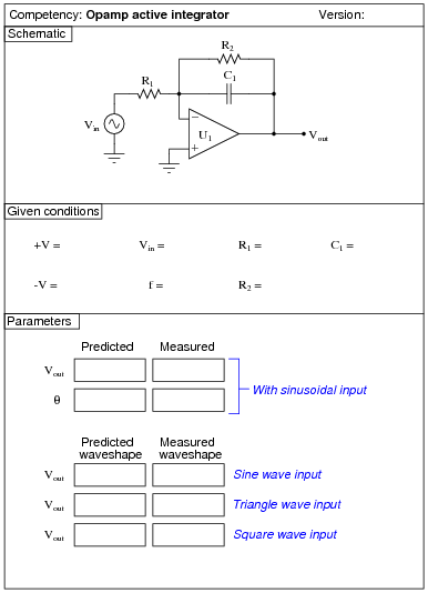
Notes:Use a dual-voltage, regulated power supply to supply power to the opamp. Specify standard resistor values, all between 1 kΩ and 100 kΩ (1k5, 2k2, 2k7, 3k3, 4k7, 5k1, 6k8, 10k, 22k, 33k, 39k 47k, 68k, etc.).
I have had good success using the following values:
- V = 12 volts
- -V = -12 volts
- Vin = 1 V peak-to-peak, at 10 kHz
- R1 = 10 kΩ
- R2 = 100 kΩ
- C1 = 0.001 μF
- U1 = one-half of LM1458 dual operational amplifier
A good follow-up activity for this circuit is to change the input frequency, and predict/measure the phase shift (Θ) between input and output for sinusoidal waveforms. The results may be surprising, especially if you are accustomed to the behavior of a passive integrator circuit.
An extension of this exercise is to incorporate troubleshooting questions. Whether using this exercise as a performance assessment or simply as a concept-building lab, you might want to follow up your students’ results by asking them to predict the consequences of certain circuit faults.
-
Question 24 of 33
Reveal answerUse circuit simulation software to verify your predicted and measured parameter values.
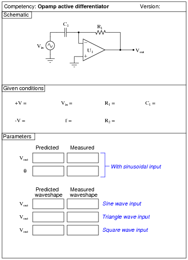
Notes:Use a dual-voltage, regulated power supply to supply power to the opamp. Specify standard resistor values, all between 1 kΩ and 100 kΩ (1k5, 2k2, 2k7, 3k3, 4k7, 5k1, 6k8, 10k, 22k, 33k, 39k 47k, 68k, etc.).
I have had good success using the following values:
- V = 12 volts
- -V = -12 volts
- Vin = 1 V peak-to-peak, at 1 kHz
- R1 = 1 kΩ
- C1 = 0.1 μF
- U1 = one-half of LM1458 dual operational amplifier
A good follow-up activity for this circuit is to change the input frequency, and predict/measure the phase shift (Θ) between input and output for sinusoidal waveforms. The results may be surprising, especially if you are accustomed to the behavior of a passive differentiator circuit.
Students may become dismayed if they see a “noisy” output waveform, especially if they have just completed the active integrator circuit exercise. Explain to them that noise on the output of a differentiator circuit is quite normal due to the proper function of a differentiator: to provide voltage amplification proportional to the frequency of the signal. This means that even a little high-frequency noise on the input will show up on the output in magnified form. Remind them that this is what differentiators are supposed to do, and it is not some idiosyncrasy of the circuit.
Active differentiator circuits are great for displaying distortions in the input waveform. While pure sine waves in should produce pure sine waves out, and pure triangle waves in should produce pure square waves out, deviations from these “pure” waveform types will produce output waveforms that obviously deviate from their ideal forms. Usually, a “distorted” output does not indicate a fault in the circuit, but rather a subtle distortion in the input signal that would otherwise go unseen due to its minuscule magnitude.
An extension of this exercise is to incorporate troubleshooting questions. Whether using this exercise as a performance assessment or simply as a concept-building lab, you might want to follow up your students’ results by asking them to predict the consequences of certain circuit faults.