Facebook
 Google
 GitHub
 Linkedin
AC Electric Circuits
Series and Parallel AC Circuits
75 questions By Tony R. Kuphaldt
-
Question 31 of 75
An AC electric motor operating under loaded conditions draws a current of 11 amps (RMS) from the 120 volt (RMS) 60 Hz power lines. The measured phase shift between voltage and current for this motor is 34o, with voltage leading current.
Determine the equivalent parallel combination of resistance (R) and inductance (L) that is electrically equivalent to this operating motor.
Reveal answerRparallel = 13.16 Ω
Lparallel = 51.75 mH
Challenge question: in the parallel LR circuit, the resistor will dissipate a lot of energy in the form of heat. Does this mean that the electric motor, which is electrically equivalent to the LR network, will dissipate the same amount of heat? Explain why or why not.
Notes:If students get stuck on the challenge question, remind them that an electric motor does mechanical work, which requires energy.
-
Question 32 of 75
Doorbell circuits connect a small lamp in parallel with the doorbell pushbutton so that there is light at the button when it is not being pressed. The lamp’s filament resistance is such that there is not enough current going through it to energize the solenoid coil when lit, which means the doorbell will ring only when the pushbutton switch shorts past the lamp:

Suppose that such a doorbell circuit suddenly stops working one day, and the home owner assumes the power source has quit since the bell will not ring when the button is pressed and the lamp never lights. Although a dead power source is certainly possible, it is not the only possibility. Identify another possible failure in this circuit which would result in no doorbell action (no sound) and no light at the lamp.
Reveal answer- Solenoid coil failed open
- Wire broken anywhere in circuit
Notes:After discussing alternative possibilities with your students, shift the discussion to one on how likely any of these failures are. For instance, how likely is it that the solenoid coil has developed an “open” fault compared to the likelihood of a regular wire connection going bad in the circuit? How do either of these possibilities compare with the likelihood of the source failing as a result of a tripped circuit breaker or other power outage?
-
Question 33 of 75
Calculate the total impedance offered by these two inductors to a sinusoidal signal with a frequency of 60 Hz:
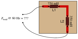
Show your work using two different problem-solving strategies:
- Calculating total inductance (Ltotal) first, then total impedance (Ztotal).
- Calculating individual impedances first (ZL1 and ZL2), then total impedance (Ztotal).
Do these two strategies yield the same total impedance value? Why or why not?
Reveal answerFirst strategy:
Ltotal = 1.1 H
Xtotal = 414.7 Ω
Ztotal = 414.7 Ω ∠ 90o or Ztotal = 0 j414.7 Ω
Second strategy:
XL1 = 282.7 Ω ZL1 = 282.7 Ω ∠ 90o
XL2 = 131.9 Ω ZL2 = 131.9 Ω ∠ 90o
Ztotal = 414.7 Ω ∠ 90o or Ztotal = 0 j414.7 Ω
Follow-up question: draw a phasor diagram showing how the two inductors’ impedance phasors geometrically add to equal the total impedance.
Notes:The purpose of this question is to get students to realize that any way they can calculate total impedance is correct, whether calculating total inductance and then calculating impedance from that, or by calculating the impedance of each inductor and then combining impedances to find a total impedance. This should be reassuring, because it means students have a way to check their work when analyzing circuits such as this!